The makings of a successful imaging lens: Part three
Part Three: Testing and metrology, ensuring you get what you asked for
Greg Hollows
Imaging and machine vision technology is under more pressure than ever to meet the increasingly demanding needs of a diverse set of markets, and truly understanding imaging is becoming quite the valuable skill.
The first part of this article series reviewed how to create a specification to meet your application need and finding the proper balance between cost, development time, system size, and weight. In part two, we reviewed how those earlier decisions translate into a design and the possible trade-offs between performance-based specifications that could be required. Finding balance between the perfect nominal design and a design that can be manufactured is critical. Finally, in this article we will cover lens testing methodology and creating alignment between validating your desired performance and your supplier’s production and testing processes.
Setting expectations during testing
Once you have your final lens design, it is critical to set proper expectations with your supplier about everything that will happen next before you cut the orders for prototypes or production units. In the earlier parts of this series, we saw that there are many details required to create your full lens specification. The specification document for your project could be 50 or 100 entries long. What is your expectation about testing every line in that matrix? Do you actually desire or require testing on only a few critical parameters? Do you want detailed, highly granular testing reports, or is pass/fail data sufficient? Is the testing methodology, philosophy, and equipment utilized important to end goals?
Taking the time to answer these questions now can prevent issues and delays from occurring later (Figure 1). Make sure you and your supplier have a detailed, written understanding of how you will both validate that the supplier delivered what you both agreed to at the end of the design process.
Figure 1: This Dilbert comic illustrates how eliminating testing from your development process can lead to disastrous results (DILBERT © 1996 Scott Adams. Used By permission of ANDREWS MCMEEL SYNDICATION. All rights reserved).
Critical testing criteria to consider
Testing your lens begins at the raw material level and continues to the detailed inspection of individual glass components and mechanical parts and ends with the characterization of a wide range of optical performance parameters of the fully-assembled lenses (Figure 2).
Figure 2: The raw material used to make individual lens components must meet certain requirements for homogeneity, refractive index, dispersion, and other properties.
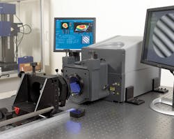
At the component level, there are tolerances that can affect the final performance of your imaging lens including surface accuracy, roughness, and centration (Figure 3). Testing throughout the fabrication process ensures the needed quality is produced. Ultimately, the combination of these tolerances is what can make your final lens not meet the desired performance criteria.
Figure 3: Interferometry is used to quantify the surface accuracy of individual glass components.
Ultimately, the testing of the completed lens assembly measures how sensitive the design is to the combination of all component tolerances. As mentioned before, it is critical to fully define the final acceptance criteria. Additionally, correlating all parties’ testing methodology and techniques can take time, creating considerable issues if it is rushed at the end of the process. There are a number of system-level tests often used to evaluate the final lens, including modulation transfer function (MTF), depth of field, distortion, and stray light.
MTF testing
MTF testing is performed on every lens assembled by nearly all manufacturers. This test quantifies how much contrast is present at different levels of resolution. Basically, it describes the crispness and clearness of an image. The first step is understanding where in the field of view (FOV) the testing should be done and how many field points should be reviewed to ensure conformance. Additionally, the wavelengths of light used can have a significant influence on the test. Different light sources have varying spectral content and will produce mixed MTF results on the same lens.
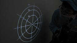
The most basic, and widely-used version of MTF testing is reverse projection (Figure 4). This is done by back illuminating a precision target that is placed at the imaging plane of the lens (the sensor location). This creates a high-contrast object in that location, which is then projected through the lens onto a wall or screen, creating a projected image in the location of the object the lens is designed to look at. This is running the lens in reverse to see its performance. The advantage of this technique is that gives a great deal of information across the entire FOV at the same time and has high-volume throughput. The downside is that it is fundamentally a subjective pass/fail test and will not produce absolute detail. As resolutions improve, it becomes more difficult to use this technique.
Figure 4: Reverse projection is the most common MTF testing method.
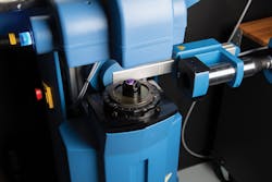
The next method of MFT testing utilizes cameras or sensors, tightly-aligned targets and objects, and software to produce more accurate detail at any given position of interest (Figure 5). This form of testing is more precise than reverse projection but much slower since it looks at discrete field points one at a time. Automation has increased throughput, but this can add cost. Additionally, it can require a more sophisticated operator than reverse projection.
Figure 5: The Trioptics ImageMaster® is a camera-based MTF measurement technique that is more precise but more time-consuming than reverse projection.
Systems that can perform these types of tests are available, but many optical companies also have developed their own in-house versions of these systems. However, these systems all use different software, hardware, light sources, and algorithms to perform their tests, which can make it difficult to correlate one system to another. This is especially true when there are complex requirements relating resolution in different areas across the image and at difference working distances.
This is where outbound testing from the supplier and inbound testing at the customer site can get complicated if not sorted out well before parts are delivered. For extremely high-volume production; streamlined, fully automated MTF systems can be developed to get the benefits of speed and fidelity, but they are usually highly-tailored systems working with a narrow group or specific product.
Depth of field testing
Testing depth of field is done by evaluating the MTF at different distances above and below best focus. This can be done with many, if not all, of the techniques described in the MTF section, but it is not always a designed-in capability of the test equipment. Typically, a specific set of criteria that matches the limitations of the test equipment needs to be developed to get accurate results. Understanding how to align with your supplier on MTF testing will make defining the depth of field testing much easier to achieve. Custom test setups may need to be developed for this test.
Distortion
Testing distortion usually requires automated systems, as visual systems that work like reverse projects struggle to create an easy pass/fail distortion condition. Many software packages are available that can be used to do this testing, but careful alignment of the sensor to the optics and mechanical alignment to the target are required to achieve proper results. Additionally, some MTF testing systems can produce distortion tests if configured correctly. Testing at the correct positions in the field is critical to ensuring that accurate results are obtained. It is easy to fail good product if this is not specified correctly.
Stray light
Stray light is the amount of unwanted light that makes it to the sensor. It is present in all lens systems and manifests itself in a couple of different ways.
It can occur when light enters the lens at angles outside the lens’ FOV and scatters off a glass or metal surface/edge onto the sensor. The result is a soft spot or a bright hot spot across the image. Reduction of this issue is done by blackening the edges of lenses, oversizing lens elements, adding sophisticated lens coatings, and inserting baffles. The trade-off will be size, weight, and likely some amount of cost. Another form of stray light can be ghost images, in which light intended to go through the lens as part of the FOV reflects between individual lens elements and eventually arrives at the sensor plane. For most machine vision applications, an intensity of 10-4 will not create ghost images, but applications with high intensity lights, laser-based illumination, or the presence of the Sun can experience detectable ghost images that would not affect most other applications.
Correcting for ghost images requires desensitizing the lens design to these issues. This is a best practice, but it reduces the degrees of freedom the optical designer can use to improve other specifications. Additionally, it will require tightly controlling antireflection coatings on the lens elements, which increases costs.
Understanding your desired end result, of course, is required to construct the proper lens specification. Testing and validation is critical to success and should be discussed up front in the project development, and at the latest, before parts are ordered. Ensure that you and your supplier are aligned on your joint test strategy. This is best way to shorten lead times, reduce headaches, and achieve the best final results.
Greg Hollows, Vice President, Imaging Business Unit, Edmund Optics (Barrington, NJ, USA; www.edmundoptics.com)
About the Author

Gregory Hollows
Gregory Hollows is the Vice President of the Imaging Business Unit in Edmund Optics’ Barrington, NJ, USA office. He is responsible for everything pertaining to vision and imaging for EO, including the business plan, strategy, and product marketing. He is also responsible for the overall growth in imaging optics sales.
He enjoys having the opportunity to affect what imaging products EO puts forth, while helping customers solve problems. The personal gratifications that come with knowing that EO imaging products are helping in many different fields and applications make all of his effort and hard work worthwhile. Gregory previously held positions as Engineering Technician and Engineering Manager. He received Bachelor degrees in Physics and Chemistry from Rutgers University located in New Brunswick, New Jersey.


