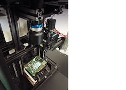
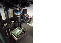
Active pattern projection improves AOI 3D measurement accuracy
3D phase shift pattern projector system combines high-resolution, telecentric lens and large-format camera.
Makoto Iwamoto
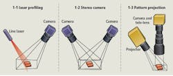
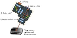
Non-contact 3D measurement can be accomplished through the implementation of various techniques. The most common methods include laser profiling with a high-power laser and line or area scan sensor, stereo camera method with two area scan sensors and active pattern projection using an area scan camera and active pattern projector (Figure 1).
Unlike single line laser/camera combinations where the laser/camera combination captures single laser line reflections as the object or scanner moves, pattern projection methods can be used to capture a complete image in a single scan without motion. That's one reason active pattern projection is gaining popularity in the machine vision market.
The other is due in large part to advancements in key hardware components such as the availability of high resolution and high-speed area scan cameras and the practicality of using electrical-optical devices called LCOS (Liquid Crystal On Silicon) and DMD (Digital Mirror Device) in imaging systems.
These two devices enable fast active pattern projection when combined with a high-power LED light source and a projection lens system. This system can project any image programmed to the LCOS or DMD device and easily synchronize the LED and camera with trigger signal allowing for a wide range of patterns for various applications.
Phase shift method
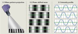
A fringe pattern, created with several wave patterns of shifting phase relationship (Figure 2), is a useful active pattern for measurement applications. The key advantages of the phase shift method include speed, coverage of a larger area, high resolution, high accuracy and robust 3D measurements when compared with laser profiling and stereo camera methods. The flexibility of the patterns enables the measurement of various samples. However, a successful solution requires a programmable active pattern projector that can quickly change several patterns and synchronize them with camera acquisition. Furthermore, combining the pattern projector with a high-resolution telecentric lens and large-format camera makes it possible to simultaneously obtain high-quality 2D images as well as different pattern projected images (Figure 1; 1-3). From these high-quality images, it is easy to analyze 2D and 3D dimensional data to confirm part dimensions, surface quality, and other important characteristics that need to be verified.
PCB fault detection
Automated optical inspection (AOI) increases the accuracy and speed of fault detection in printed-circuit-board (PCB) production. Formerly, high-speed 2D area inspection was commonly used due to its ease of implementation. Recently however, with continuously shrinking components, increasing PCB feature complexity and more stringent quality requirements, 3D inspection has become necessary for high-end PCB manufacturers such as those supplying the consumer electronics and automotive markets.
Figure 1: 1-1: Laser profiling systems combine a line laser and area scan camera. Here the sample or laser must move to scan a profile. 1-2: Stereo camera systems require different angles between two area scan cameras, like the human eye. 1-3: Pattern projection systems include a pattern projector, standard telecentric lens, and area scan camera. Often a multi-projector setup, arranged at different angles, can reduce projection shadows.
Figure 2: 2-1: Wave pattern projection is used in the phase shift method. 2-2: Phase shifted patterns view from camera. 2-3: Intensity profile of phase shifted patterns.
In consumer electronic applications such as mobile and wearable devices, end-product size is becoming smaller and thinner year by year. With those changes requiring even smaller electrical components, it has become very difficult to find incorrectly-mounted parts with only 2D inspection and nearly impossible to characterize and measure them in a crowded assembly.
In the automotive market, the number of electrical parts on a car increases each year. At the same time, the safety requirements are very high because of the potential impact on human life especially high voltage or high temperature electrical parts.
Additionally, automotive electrical parts may be larger with more complex shape/dimensions versus standard consumer electronics parts. 3D inspection is necessary for these complicated parts to ensure they are successfully mounted and that they are secure in the correct arrangement.
Projector for 3D measurement
For high speed and high accuracy 3D measurement with active fringe patterns, a projector able to provide high brightness and high contrast patterns is required. Such solutions are made possible when machine vision suppliers, such as Moritex (San Jose, CA, USA; www.moritex.com), are able to design, integrate, and manufacture a projection system using high-performance lens and LED illumination technologies (Figure 3).
Figure 3: 2-1: Pattern projector systems combine a high-resolution, telecentric lens with a large-format camera.
The first step is to choose the appropriate LED for high-brightness output of the pattern, such as an LED with a 15-100 W output. Then, optics are designed to maximize the output of the LED and couple with the DMD or LCOS device. Finally, after the light path is optimized, the projection optics for focusing the pattern are designed to meet the imaging system parameters such as field of view, working distance, brightness, and resolution.
Keep in mind, the maximum brightness is important to increase the measurement speed. The projected patterns' resolution and contrast are also very important to enable high accuracy 3D measurement over the full measurement area.
Figure 4: The Scheimpflug principle is useful to keep the horizontal focus plane orientation with angled projection (left). Without the Scheimpflug arrangement, a loss of contrast at the image edge (right) may have a considerable effect on 3D measurement accuracy.
When comparing the capabilities of 3D phase shift pattern projector suppliers, it's important to evaluate the level of expertise in designing each sub-system to meet a specific purpose. Also, consider the supplier's experience integrating such subsystems into a complete, all-in-one solution that meets challenging application requirements. Finally, be sure the supplier has experience utilizing the Scheimpflug principle because for many applications, it is quite useful to keep the horizontal focus plane orientation with angled projection (Figure 4; left). Without the scheimpflug arrangement, a loss of contrast at the image edge (Figure 4; right) may have a considerable effect on the 3D measurement accuracy.
A powerful combination for high accuracy 3D measurement includes (Figure 1; 1-3):
• High-resolution object-side telecentric or bi-telecentriclens
• High-speed, large-format camera, pixel size matched tolens
• High-contrast angled projector based on Scheimpflugprinciple
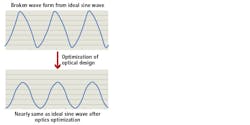
The reproducibility of the projected sine wave is also very important to maintain high accuracy with the phase shift method (Figure 5). Through expertise in lens design technology, it is possible to optimize the projected sine wave reproducibility.
Figure 5: Optical design optimization maintains projected sine wave reproducibility to deliver high accuracy with the phase shift. method.
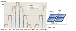
One major concern for system design is that the DMD devices have a gap between each mirror (Figure 6; right). This also has a strong effect on the sine wave reproducibility (Figure 6; left). Because the mirror gaps cannot reflect light, there is a drop in brightness between each mirror and the output becomes darker than ideal.
Figure 6: Because the gaps between each mirror (right) in DMD devices don't reflect light, brightness drops resulting in darker than ideal output. For high accuracy 3D measurement, a high-density pattern pitch wave must be used with the high-resolution camera (left). If camera resolution is too high, however, then the gap effect becomes greater.
For high-accuracy 3D measurement, a high-density pattern pitch wave must be used with the high-resolution camera. If camera resolution is too high, however, then the gap effect becomes greater. Through optimization of the optical systems, Moritex has been able to successfully reduce the DMD gap effect in its solution.
3D Measurement
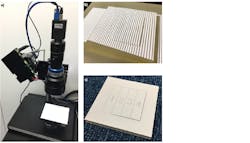
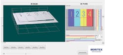
Figure 7a shows an example of a phase shift 3D measurement solution with Moritex active pattern projector and Moritex bi-telecentric lens. The test sample was made by 3D printer and painted white, with four physical steps and each step height is 200 μm (Figure 7c). Figure 7b shows the projected sine wave pattern on the test sample which is typically of that used in the phase shift method.
Figure 7:(a) Moritex system solution (FOV 32 mm) setup includes WXGA DMD projector, 4MP 1inch USB3.0 camera, and 0.34x Bi-telecentric lens MTL-5518C. (c) Test Sample made with 3D printer and painted white. Each step height increase is 200 um and step XY dimension is 25 mm x 9 mm. (b) Projected sine pattern on sample based on phase shift method concept.
After careful calibration of the system, the 3D measurement test result is shown in Figure 8. This system is able to measure a 200-μm height difference over the field of view (FOV) of 32 mm x 32 mm.
With repeatability tests, Moritex found that the standard deviation is 2 to 5 μm. The measurement time is approximately 1-2 seconds, with the number of data points 2048 x 2048. This solution shows that it is possible to measure wide FOV objects at high resolution and high speed with high accuracy.
Figure 8: 3D measurement results in the 3D model data (left), 2D color map based on height (top right), and 2D profile (bottom right) based on the red-cross lines on 2D profile map image.
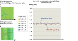
Figure 9: Left side is 3D measurement data of flat plate on 5 mm (height). Left top is 3D height map data by projector reducing DMD gap effect by special optics. Left down is 3D height map data by projector with DMD gap effect. Right side is 2D line profile comparing reducing DMD gap effect and with DMD gap effect.
If there is a DMD mirror gap effect on projection, the measurement 3D data result will have some artifacts (Figure 9). The data in Figure 9 is the height measurement of a flat plate. The height setting of the flat plate is 5mm while the standard deviation of height on the 2D area by the projector designed with the DMD gap effect reduction is just 3 μm on 5 mm object.
On the other hand, the standard deviation of height on 2D area by a projector with a DMD gap effect is 9 μm which is a factor of 3x. Also, even though the actual sample is just a flat plate, there is still an artifact on the wave surface on the 3D data caused by the DMD gap effect. In that case, with the Moritex projector it is possible to reduce DMD gap effect to achieve projector optics that deliver high accuracy 3D measurement.
Makoto Iwamoto is 3D Product Manager at Moritex North America, Inc. (San Jose, CA, USA; www.moritex.com).
