Using coaxial-brightfield illumination to improve 3D measurements
While coaxial-brightfield illumination offers significant benefits in 3D measurement applications, it’s important to factor in the working distance and image quality trade-offs involved.
Timo Eckhard
Choosing the right illumination is critical for acquiring high quality images needed for calculating 3D data. This has typically been accomplished with directional-coaxial-brightfield illumination or a tube light. This article compares these two methods of illumination in terms of color image quality and height map using a variety of samples.
It could be shown that for material that exhibits considerable amounts of subsurface scattering, coaxial-lighting geometry benefits the 3D measurement. In practice, it should be kept in mind that introducing a beam splitter in the light path results in a shift of the working distance of the camera system, and a slight reduction of image quality.
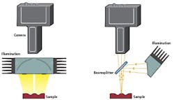
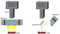
Figure 1: Sketch of tube light illumination (left) and coaxial brightfield illumination (right).
An illumination scheme where the source rays are reflected from a flat sample directly into the camera is called a brightfield. With line scan cameras there are two possible ways to realize such a setup: either by tilting the camera and light source such that the angle with respect to the surface normal is the same but opposite direction, or by using a beam splitter. The first method is not recommended as it can lead to occlusion and keystone effects.
Figure 1 shows the principle of the coaxial-brightfield-illumination setup using a beam splitter in comparison to a setup with a tubelight. The tube light is the superior illumination choice for a wide array of possible applications. It reduces the intensity of specular reflections and evenly illuminates curved glossy materials. Consequently, the tube light is a popular first choice for many applications and only some materials require the use of a coaxial-brightfield illumination.
An example is material that exhibits strong subsurface scattering, which means that light beams partially penetrate a material in a certain direction and are scattered multiple times, resulting in them exiting at a different location with possibly a different direction. The outcome is a material appearance that is translucent. Examples of such materials are marble, skin, wax or some plastics.
Using a tube light on such materials results in a very homogeneous appearance with little texture, which is problematic for 3D reconstruction. Employing coaxial-brightfield illumination results in relatively more direct reflection from the surface to the camera, as compared to tube light illumination. This first surface reflection contributes to the image texture; the relative amount of sub-surface scattered light entering the camera is thereby reduced.
There are some specific properties that have to be taken into consideration when using a coaxial setup with a 3D camera. For the purpose of this test, a Chromasens 3DPIXA stereo camera was used. First, only a maximum of 25% of the source intensity can reach the camera as the rest is directed elsewhere in the two transits of the beam splitter. Second, the glass is an active optical element that influences the imaging and 3D calculation quality. Later, this article will take a closer look at these factors and offer some guidelines for mechanical system design to account for resulting effects. But first, a discussion of the effects of the brightfield illumination on a selection of samples will set the stage and provide an idea of when this type of illumination setup should be used.
Comparing brightfield and tube light illumination
To capture the differences between the two illumination methods with different samples, the Chromasens CORONA II Tube light was used, and for brightfield, the CORONA II Top light with diffusor glass was used together with a beam splitter made from 1.1 mm Borofloat glass from Schott North America (Elmsford, NY, USA; www.us.schott.com).
Figure 2 shows a scanned image of a candle made of paraffin, which is a material that exhibits strong subsurface scattering. With coaxial illumination (right image) the surface texture is clearly visible and the height image shows the slightly curved shape of the candle.
In comparison, the tube light (left image) contains very low texture. Subsequently, height information could not be recovered for most of the heights (black false-colored region). The texture is only visible with coaxial illumination because under this condition the light reflected from the surface is more dominant in the final image than the subsurface scattered light.
However, the ratio between these two effects varies with different surface inclinations. The more deviated the surface normal is from the camera observation angle, the less direct light is reflected directly from the first surface. Therefore, texture in the image gets lower. For the candle sample, more than 15° deviation resulted in failure in recovering height information. This can be seen in the right image at the outer edges of the candle.
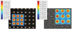
The next example is an electronic circuit board substrate material, an often-translucent appearing plastic with a glossy surface. A scanned sample is shown in Figure 3.
The substrate area in the tube light image (left) shows low texture, resulting in partially low performance height reconstruction (black points in false-colored image overlay). With coaxial illumination (right image), the amount of source rays reflected back into the camera from the surface of the material is larger than the subsurface scattered light. The image texture is higher and height reconstruction performance improves.
However, if the height of the balls is the focus rather than inspecting the substrate, the situation becomes more complex as the coaxial illumination results in specular reflection on the ball tops. If these areas are saturated, it negatively affects height measurements as well.
The best illumination therefore strongly depends on the measurement task and materials used and can often only be determined by testing.
Optical Influence
A beam splitter essentially is a plan parallel glass plate that offsets each ray passing through without changing its direction. The size of this offset depends on the incidence angle, the thickness of the glass and its refractive index. The thickness of the beam splitter should therefore be only as small as is needed for stability reasons. In the following analysis, it is assumed that the thickness of the Borofloat glass in beam splitter is d = 1.1 mm.
The result of the beam splitters’ influence is a movement of the point from where the sharpest image can be acquired in all three spatial coordinates. The change along the sensor direction (called x direction) leads to a magnification change of the imaging system that is negligible (< 0.4 %, with a small dependence on camera type).
Figure 3: Images of a ball grid array with false color height inset using tube lightning (left) and coaxial illumination (right). Camera: 3DPIXA with 15μm lateral resolution; CP000470-C01-015-0040
The change along the scan direction (called y direction) only offsets the starting point of the image. If the exact location of the scanline is important i.e., when looking on a roll, the camera needs to be displaced relative to the intended scan line by
Δy = d*(0.30n – 0.12).
The equation is valid for all glass thicknesses d and is a linear approximation of the real dependency on n, where n is the refractive index of the glass material introduced into the light path. The approximation is valid in the interval of n= [1.4, 1.7] and for all types of 3DPIXAs. The direction of the displacement is towards the end of the beam splitter that is nearer to the sample, so in the scheme in Figure 1 the camera has to be moved to the left.
The change of the working distance is different along the x- and y-axis of the system because of the 45° tilt of the beam splitter leading to astigmatism. In ydirection, the working distance is increased by
Δzy = +d*(0.24n +0.23).
As above, the formula is valid for all d and n= [1.4, 1.7]. The change of the working direction along the xdirection is not constant but also changes depending on the position of the imaged point which leads to field curvature. Both astigmatism and field curvature slightly lower the image quality, which influences the imaging of structures near the resolution limit. But they should not influence the 3D algorithm, as generally only height structures that are several pixels in size can be computed.
Additionally, to the optical effects discussed above, the beam splitter also changes the absolute height values computed by the 3D algorithm, i.e., the absolute distance to the camera. The exact value of this height change is slightly different for each camera. Generally, the measured distance between camera and sample decreases, so that structures appear nearer to the camera than they really are.
This change is constant over the whole height range with simulations showing 0.2 % change, and also constant over the whole Field of View. In summary, relative height measurements are not influenced at all, and absolute measurements are shifted by a constant offset.
As the precise change of the calculated height is not known, the zero plane of the height map can’t be used to adjust the camera to the correct working distance. It is advised to instead set up the camera using the free working distance suggested by the manufacturer and correcting it with Δzy from above.
Summary
On certain translucent materials, that is, those exhibiting considerable subsurface scattering of light, using coaxial illumination can result in a significant increase in image texture which greatly benefits the 3D height reconstruction. However, the additional glass of the beam splitter in the optical path of the camera system when using coaxial illumination influences the optical quality negatively. Further, the working distance of the system changes slightly and the absolute measured distances are set off by a constant value.
Timo Eckhard, Innovation and R&D manager for Chromasens (Konstanz, Germany; www.chromasens.de)


