Novel lenses bring new insights to bottle inspection
Using a combination of hole and pericentric lenses enables inspection of glass bottles at speeds of up to 120 parts per minute.
David L. Dechow
Whether they be glass blown or molded, manufacturers of glass bottles for the food and pharmaceutical industries must ensure that there are no defects in the products that they ship. Indeed, before such products can be filled, defects such as cracks in the rim, alongside walls or the bottom of the glass must be carefully inspected. Furthermore, such inspections should take into account whether any glass shards are present in the bottle, whether any foreign material is present and whether the threads and thread sealants have been properly formed.
To accomplish this on production lines that produce glass jars at rates of up to 120 parts per minute is a demanding task that calls upon sophisticated machine vision systems that use novel lensing techniques. When tasked with developing such a system for a leading manufacturer of glass containers, Integro Technologies (Salisbury NC, USA (www.integro-tech.com) needed to build a system that could inspect a number of different sizes of glass bottles for such defects.
Major challenges in developing the system were to inspect both the thread of the glass for missing threads and cracks, as well as checking the inner wall of the bottle for cracks, dirt and foreign material.
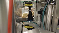
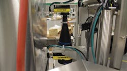
To accomplish this task, Integro Technologies built a machine vision system using two cameras that could be automatically configured to accommodate the needs of the different types and styles of the manufacturer’s products. (Figure 1). A video of the system in operation can be found at http://bit.ly/VSD_GIV. As products were automatically singulated from the customer’s production line, there was no need to perform this task in the inspection system.
Figure 1: Integro Technologies has built a machine vision system using two cameras that can be automatically configured to accommodate different sizes of glass products.
Thread inspection
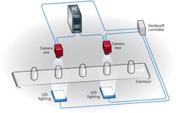
To inspect the threads of the bottles and the inner wall of the bottles, two integrated inspection tasks are performed. As the bottles move from the manufacturing processes, they are first cooled and singulated. As the glass containers approach the first inspection station, a photoelectric sensor is used to trigger both an LED controller from Gardasoft Vision (Swavesey, Cambridge, UK; www.gardasoft.com). This, in turn, is used to strobe a red LED backlight from CCS America (Burlington, MA, USA; www.ccsamerica.com) that is placed under the conveyor belt to back illuminate the jar. Simultaneously, the Gardasoft controller is used to trigger a smart camera from Cognex (Natick, MA; USA; www.cognex.com) that is interfaced to a host PC (Figure 2).
Figure 2: In the design of the system, two camera systems are used to inspect the outside and inside of the glass containers that are back illuminated with red LED panels. A Gardasoft controller is triggered by the parts as they move through two photoelectric sensors at each station. This then strobes the LED panels and triggers the cameras.
To inspect the threads on the outside of the glass, whether the side surfaces exhibit any defects or scratches and whether the locking notch is properly formed, multiple machine vision camera systems could have been deployed to image both the sides and top of the container. In this case, however, a more elegant single-camera solution using a single pericentric lens from Opto Engineering (Mantova, Italy; www.opto-engineering.com) was used to image the outer threads and wall of the glass.
Because the depth of focus is very short, it was necessary to place the lens at a precise distance from the glass container. However, since various different-sized containers all with different heights needed to be accommodated, it was necessary to place the camera system onto a custom-built precision linear ball screw drive mechanism so that it could be precisely positioned at different heights. This slide mechanism has a small servo-controller programmable motor that is controlled by the system’s PLC over Ethernet/IP.
Images are captured and processed by high-resolution In-Sight cameras from Cognex. Images of the outside of the glass container are then displayed on the system’s host PC (Figure 3). As can be seen, the image taken with the pericentric lens displays the outside of the container with the threads displayed at a radial angle. Thus, the continuous thread of the jar can be seen.
Figure 3: Images of the outside of the glass container taken with the pericentric lens display the outside of the container with the threads displayed at a radial angle.
To process this image to detect any defects, annular regions of interest (ROIs) are first placed around the image. Once these inspection areas have been located, a polar unwrap is performed and the area is evaluated using line analysis tools to determine if a thread defect is present. If such a defect is found, then the glass container will be rejected later from the conveyor.
Hole inspection
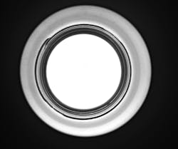
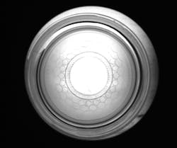
After the outer surface of the glass container and outer threads are inspected, the container moves along the conveyor to the second inspection station. Here, a blue LED backlight from CCS America is again triggered by the Gardasoft controller. Simultaneously, a Cognex industrial camera with a 5 MPixel CMOS image sensor is used to image the part. Here, however, since it is necessary to image the inside, rather than the outside of the glass jar, the camera is fitted with a hole inspection optic lens, also supplied by Opto Engineering. Unlike standard lenses that can only image flat fields of view, this hole inspection optic is designed to image both the vertical walls and the bottom of the container.
Using this hole-inspection lens, is it possible to image the inside of the object and visualize the inner wall for the presence of dirt, cracks, foreign material or any glass shards that may be inside the jar. This same lens also allows the camera to image the lower part of the glass to check whether any defects are present on the bottom of the container (Figure 4).
Figure 4: Using a hole-inspection lens, is it possible to image the inside of the object and visualize the inner wall for the presence of dirt, cracks, foreign material or any glass shards that may be inside the jar.
In one implementation, at the bottom of one glass jar, the manufacturer molded a design at the edges to make it visually aesthetic. When imaged with the hole inspection optic lens, this molding appears as a honeycomb pattern within the image. Since this is not a defect, it must be removed before any image processing algorithms can be used to inspect the inside of the glass jar.
To accomplish this, a pattern locate algorithm was used to facilitate masking of the honeycomb feature. Then, regions of interest are also placed around the edges of the image that isolate the lower sidewall of the container. Blob analysis is then used again at this second station to discern features that would indicate that the lower sidewall is not formed correctly or, for example, that shards of glass may be present within the glass container and thus the part must be rejected.
After both the outside and inside of the glass containers are inspected, a pass/fail decision is made and used to reject any bad parts. To perform this task, the manufacturer required that the parts be rejected in such a way that they were not broken but could be, for example, cleaned and returned to the conveyor for further inspection or manually inspected.
A sophisticated operator user interface (UI) was used to provide information about the process and to handle the many multiple inspection configurations necessary for different part types and sizes.
The UI in this system was a PC-based program specifically designed for complex vision system/control system communications and interfacing. The UI displays and annotates each camera image as it is processed. It also communicates inspection configuration recipes with the PLC and cameras to adjust inspection parameters and physical camera position. The UI provides a convenient interface to the camera software configuration environment to facilitate configuration of new, or modification of existing inspection recipes for the system.
If a part is assumed to be a defect, then the programmable logic controller is used to trigger a sliding door mechanism that directs parts into a reject bin. Parts that are deemed to be good then travel along the conveyor belt to further automated systems where they are filled, labeled and capped.
David L. Dechow, Principal Vision Systems Architect, Integro Technologies, Salisbury NC, USA (www.integro-tech.com)
Companies mentioned
CCS America
Burlington, MA, USA
Cognex
Natick, MA, USA
Gardasoft Vision
Swavesey, Cambridge, UK
Integro Technologies
Salisbury NC, USA
Opto Engineering
Mantova, Italy
