The makings of a successful imaging lens: Part two
Part Two: Performance-based specifications and their design considerations
Greg Hollows
Imaging systems play a critical role in almost all the technical innovations around us. Advanced medical devices require imaging to correctly diagnose and treat patients, autonomous vehicles need to be able to accurately detect their surroundings, and semiconductor manufacturers depend on imaging to create the integrated circuits that drive so much of today’s technology.
The first part of this three-part article series focused on understanding a given imaging application and the impact of cost, schedule, size and weight of the appropriate imaging solution. This article will cover performance-based specifications, such as resolution, distortion, as well as parameters like field of view and working distance and their associated design considerations.
Imaging system designers don’t always use the same terminology as the engineers asking them to design lenses and misunderstanding what is meant by lens specifications can lead to lens systems not meeting the specifier’s expectations (Figure 1). Achieving high levels of performance for one specification can require changes to other desired specifications and working through these details early on produces desirable system results.
Figure 1: This Dilbert comic illustrates how a misinterpretation of exactly what is meant by a request can lead to less than favorable results (DILBERT © 1994 Scott Adams. Used By permission of ANDREWS MCMEEL SYNDICATION. All rights reserved).
Fundamental parameters of an imaging system
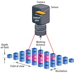
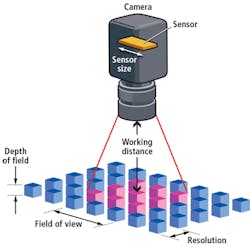
There are a wide range of technical specifications built into a final lens design. While they are standalone requirements, they are interconnected and changing one can and usually does affect others. The foundation of a lens specification should start with the fundamental parameters of an imaging system: field of view, working distance, resolution, depth of field, and the sensor size (Figure 2).
Figure 2: This illustration shows the fundamental parameters of an imaging system.
Field of view (FOV): The extent of the object under inspection that fills a camera’s sensor and is viewable. It is likely the most straightforward parameter of most systems, but issues can arise when also considering the working distance or total tract of the system, as outlined below. Problem areas arise in systems designed to look at wide angular FOV’s. While every system is different, performance issues often arise once the angular FOV approaches 30° or greater. At extreme angles, above 60°, significant compromises are needed to balance FOV with other specifications.
Working distance (WD): The distance from the front of the lens to the object being imaged. As a standalone parameter, WD by itself is usually not an issue. Conflicts arise when balancing it with FOV. It can be very difficult to achieve the desired resolution or distortion specifications if the WD and FOV are close to the same value. When they are equal, the angular FOV approaches 60°. If the WD is smaller than the FOV, it becomes even more difficult to achieve acceptable levels of resolution and distortion.
For optimal balancing of all other performance parameters, including cost, a target WD that is at least twice the desired FOV should be used. However, a WD that is significantly larger than the FOV (10x or more), can also create issues in hitting performance, size, and cost specifications. Finally, it is more straightforward to create a design which is designed to work at one WD rather than a range of them.
The more range of WD required, the more complex the design becomes.
Resolution: The minimum object feature size that can be distinguished by the imaging system. The ability to see the detail is directly related to the contrast produced at that detail level. The relationship between the spatial frequency of object details and contrast is known as the Modulation Transfer Function (MTF). As pixels get smaller, the ability of the lens to reproduce resolution and contrast decreases. This is a physics-based limitation of lens design.
Fundamentally, optics are the bottleneck in the system, especially with smaller pixels. There are changes that can be made in the lens design to improve this issue, but it is usually at the expense of depth of field (DOF), size, and the lens-cost structure.
Utilizing a larger sensor with larger pixels is a better system-level solution. The tradeoff here is that sensors with larger pixels can come with higher cost and potentially larger camera footprints. Additionally, as outlined above, wide FOVs at short WDs will reduce the resolution capabilities of a lens. Finally, low levels of distortion are beneficial to most systems. Improvement in distortion tends to hurt the resolution, and vice versa. Tradeoffs between resolution and distortion are highly pronounced in wide angular FOV systems.
Depth of field (DOF): The maximum object depth through which acceptable focus can be maintained. DOF describes the amount of movement in and out of best focus possible while maintaining the desired detail level. DOF, like resolution, also has physical limitations associated with it. Improving DOF requires a change to the system that reduces resolution, and improving resolution reduces DOF. The bottom line is that achieving great DOF and high levels of resolution at the same time cannot be easily achieved, especially when using smaller pixels. Moving to larger pixels is one of the best ways to relax the conflict that arises between resolution and DOF.
Sensor size: The dimensions of the active area of a camera sensor, usually specified in the horizontal dimension. Sensor size helps determine the required lens magnification needed to obtain a desired FOV. Hand and hand with the sensor size is the pixel size. As outlined previously, systems with smaller pixels will have a hard time producing higher levels of contrast. While bigger sensors with bigger pixels do improve system performance, they are usually more expensive. Determining the needed sensor early on is critical for reducing design time and upfront design costs. Switching from one sensor to another can require a lens design to be restarted from the beginning.
Other Important Specifications
Some other specifications that are necessary to consider during lens development include distortion and waveband.
Distortion: A simple definition of distortion is the misplacement of object information imaged onto the sensor. Lenses with larger fields of view will generally exhibit greater amounts of distortion. As noted previously, there tends to be a tradeoff between distortion and resolution. To minimize distortion while maintaining high resolution, the complexity of the design must be increased. This can typically be accomplishd by adding more optical elements to the design or by using more complex optical glasses or other fabrication techniques, such as utilizing aspheres.
However, high levels of distortion control can also affect the evenness of the illumination across the field of view, known as relative illumination (RI). This is seen as changes in brightness levels across the sensor when visualizing an object of uniform brightness. This produces undesirable effects in the system, especially in systems doing critical measurements or intensive software analysis. Illumination flatness and RI should be discussed early in the development process. They cannot be easily adjusted after the design is complete and could require a complete redesign of the lens if the results are unsatisfactory.
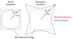
In many lenses, there are two main types of distortion: positive, barrel distortion, where points in the field of view appear too close to the center; and negative, pincushion distortion, where the points are too far away. Barrel and pincushion refer to the shape a rectangular field will take when subjected to the two distortion types, as shown in (Figure 3). Lenses that have high levels of distortion correction usually contain both negative and positive distortion across the FOV.
Figure 3: Positive and negative distortion are shown here.
Finally, there are different ways to technically specify the distortion of a lens, i.e. geometric distortion or CCTV distortion. The different forms of these specifications are meant for the intended application of the lens. While always given as percentages, the different specification types cannot be compared to each other. For almost all cases except for security and photographic applications, geometric distortion is the best choice for specifying distortion.
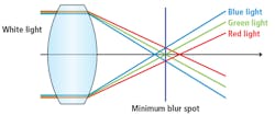
Wavelength range (Waveband): The wavelength range that a lens is designed to cover is a very critical parameter of the technical specification. Chromatic aberrations cause lenses to struggle to perfectly focus different wavelengths to the same position on the sensor. Chromatic aberrations are primarily classified into two types: transverse (across the sensor) and longitudinal (closer to or further away from the sensor (Figure 4 and Figure 5). Transverse chromatic aberration is commonly referred to as lateral color, as the lateral position of the information across the sensor changes with the different wavelengths.
Figure 4: Shown in this image is transverse chromatic aberration of a single positive lens.
Longitudinal chromatic aberration is also called chromatic focal shift, as the actual focus position shifts at different wavelengths. Both issues result in the loss of contrast at a given resolution because parts of the object detail are spread or blurred across multiple pixels. The wider the wavelength range, the harder it will be to achieve maximum performance. These effects can be mitigated by utilizing larger pixels, more lens elements, more complicated lens geometries, or more expensive glass materials. No one “silver bullet” can maximize performance in all cases and all of these have increased cost associated with them.
Figure 5: Longitudinal chromatic aberration of a single positive lens is highlighted here.
Understanding these performance specifications and the tradeoffs between them will ensure that the proper imaging system parameters are chosen to optimize performance and cost. Taking the time to do robust specification development up front and ensure that all parties understand what they mean is critical to completing the design in a timely fashion. If the application has rigorous demands in many of the areas listed above, a design that fully meets all the requirements could be untenable or very difficult to manufacture. The third, and final, part of this article series will cover lens fabrication, assembly, testing, performance evaluation, and why designs can take a performance hit in production.
Greg Hollows, Vice President, Imaging Business Unit, Edmund Optics (Barrington, NJ, USA; www.edmundoptics.com)
About the Author

Gregory Hollows
Gregory Hollows is the Vice President of the Imaging Business Unit in Edmund Optics’ Barrington, NJ, USA office. He is responsible for everything pertaining to vision and imaging for EO, including the business plan, strategy, and product marketing. He is also responsible for the overall growth in imaging optics sales.
He enjoys having the opportunity to affect what imaging products EO puts forth, while helping customers solve problems. The personal gratifications that come with knowing that EO imaging products are helping in many different fields and applications make all of his effort and hard work worthwhile. Gregory previously held positions as Engineering Technician and Engineering Manager. He received Bachelor degrees in Physics and Chemistry from Rutgers University located in New Brunswick, New Jersey.


