Reverse-geometry x-ray inspection finds aircraft cracks
Reverse-geometry x-ray inspection finds aircraft cracks
By Lawrence J. Curran, Contributing Editor
The inspection of aging aircraft for cracks and corrosion that could cause catastrophic failures has been a time-consuming but essential task for the military services and commercial airlines alike. However, an innovative x-ray inspection system developed by Digiray Corp. (San Ramon, CA) has proven able to detect aircraft flaws more quickly, accurately, and conveniently than previously used inspection methods.
Indeed, the Digiray Reverse-Geometry X-ray (RGX) inspection system is being used by the US Air Force (USAF) to detect defects in the advanced composite materials used in the F-117 stealth fighter. Another RGX user is
the team of Northrop Grumman Corp.`s Surveillance & Battle Management Systems organization and NASA Langley Research Center. Northrop Grumman reports encouraging results from tests conducted on wing structures similar to those of aging Boeing 707 aircraft that the USAF plans to refurbish. The RGX system has detected aircraft cracks and corrosion faster and without the costly removal of wings or other assemblies required by conventional x-ray systems or with other inspection methods, such as ultrasonic and eddy current.
How it works
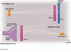
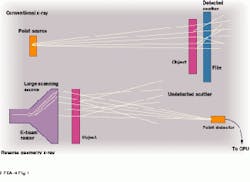
Dick Albert, founder and president of Digiray, says the best way to understand reverse geometry is to compare it to standard x-ray radiography. In standard practice, the object to be imaged lies between a point source of x-rays and a large film sheet. The object`s absorption and deflection of x-rays produces a shadow on the film, placed directly behind the object. In addition, the object must be placed far enough away from the small source to allow the x-rays to spread. And the object must be close enough to the detecting medium to remain in focus (see Fig. 1 top).
Albert says many x-rays that should be blocked by the object are merely deflected in such a way that they strike in the wrong place. "This scattering causes fogging, compromising the quality of conventional x-rays," he says.
With reverse-geometry technology, the object is moved far enough away from the detecting medium so that most of the deflected x-rays dissipate harmlessly. And the detectors can be made very small, preventing the pickup of off-course x-rays, thereby virtually eliminating image degradation.
Digiray utilizes an x-ray source that uses the raster of a tube that is shaped like a television picture tube (see Fig. 1 bottom). This tube is made large enough to illuminate an object placed close to it. The source comprises scanning electron-beam tubes "with several points of origin for x-rays" that Digiray manufactures, Albert reports.
Direct digital imaging
Albert states that raster scanning, together with computer-stored digital data from the detector unit, represents a radical change in the way images are made. Unlike a film sheet or image-intensifier screen, reverse-geometry technology "reads and writes" first-generation digital images that are stored in the RGX system`s 200-MHz Pentium-based personal computer.
The reverse-geometry x-ray source incorporates the same electronic principles used in a cathode-ray tube (CRT). That is, electrons are swept in a raster pattern across the target of a broad anode plate. The x-rays originate from this moving point of impact. The 1-ms/pixel readout rate of the detector unit is synchronized with the beam sweep of both the source and the CRT monitor.
The monitor can display images at various resolutions and frame times, such as 512 ¥ 512 pixels at 0.25 s; 1024 ¥ 1024 pixels at 1 s, and 2048 ¥ 2048 pixels at 4 s. Because the detector unit provides a digital output, digitization occurs before imaging and preserves the high signal-to-noise ratio. This high ratio provides the contrast that underlies the system`s ability to detect subtle defects, such as fatigue cracks. Because the first-generation image is directly digitized, the RGX method eliminates the need for x-ray film, the time to develop it, and the need for image intensifiers or vidicons.
When using the RGX system, alignment of the x-ray source, object, and detector is not critical. And because x-rays are emitted over a wide angle, considerable flexibility is achieved in detector alignment (䕑) and detector tilt. "As long as the x-rays can reach the detector, the computer can produce a radiograph correlating the source/object space with raster time," Albert says.
Moreover, the exposure setting is also not a critical issue because of the detector`s wide dynamic range. In practice, a scintillating crystal detector coupled with a photomultiplier tube results in two bits of gray-scale latitude. Users can therefore access 4096 shades of gray or 256 false-color hues.
Stereoscopy and laminography
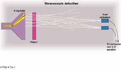
The RGX inspection system can also display real-time images in stereoscopic three dimensions--a procedure that requires two detectors (see Fig. 2). The amount of separation between the detectors determines the strength of the three-dimensional effect. The radiographer wears polarized glasses to view a display monitor with a polarized shutter. Quantifiable measurements of length, area, and depth can be made in three dimensions.
Albert says Digiray has also added laminography to the RGX system, borrowing a technique from medical radiography. By using multiple detectors and arithmetically combining their outputs with their locations, laminography can view one layer at a time within the object. "This effectively peels away the outer layers of the object and examines what lies below the surface," Albert explains. "With RGX laminography, we can take slices at any angle through an object by rotating it," he adds.
Inspecting wing sections
As part of a USAF-sponsored Engineering Support Task, Northrop Grumman Corp.`s Surveillance & Battle Management Systems (SBMS) organization (Melbourne, FL) discovered the RGX system while conducting a survey to find advanced nondestructive-testing technologies. The SBMS group was seeking more efficient methods to inspect the lower wing sections on USAF Joint Stars aircraft. Joint Stars is a program that plans to use refurbished Boeing 707 aircraft as near-to-ground surveillance platforms to examine land surface features.
During its technology survey, SBMS evaluated thermal imaging, acoustic emission, eddy current, visual inspection and conventional radiography testing methods. It concluded that none of them met its needs. "Each of these [technologies] is limited in detection of defects," says William Pember, SBMS lead engineer in materials process engineering. In the eddy-current inspection method, fasteners must be removed, and inspection time runs six minutes or more per fastener hole. In the visual-inspection method, viewing of critical areas is limited to external layers, and the surfaces to be inspected must be cleaned of paint and coatings; consequently, large subsurface flaws can go undetected.
As for conventional x-ray inspection systems, Pember points out that film-placement restrictions can require object disassembly for rear access. Furthermore, it is impossible to inspect under steel fastener heads, and the immediate area must be evacuated to prevent worker exposure to radiation. Ultrasonic inspection limits the depth of inspection coverage, and requires skilled operators and image interpretation.
The RGX way
The SBMS survey discovered two unconventional x-ray systems that appeared able to do the required inspection job: the Digiray RGX system and Phillips Electronics Comscan`s BackScatter x-ray system. "After reviewing these two, we selected the Digiray RGX as the most promising for widespread fatigue evaluation," Pember says. However, the Phillips system is being used successfully in production lines to check for corrosion and cracks in thinner aircraft structures.
The SBMS group developed a multiphase test plan for the Digiray system involving test specimens with flaws that were both machine induced and naturally fatigued and under simulated worst-case conditions. During Phase I, the RGX system successfully detected notches measuring 0.020 ¥ 0.020 in. and 0.020 ¥ 0.100 in. at a depth of 0.800 in. During Phase II, the RGX system also was able to detect load-induced fastener hole cracks estimated at more than 0.100 in. deep in a lower wing section.
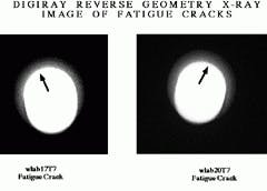
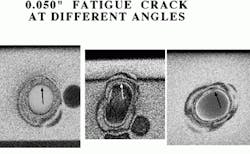
The RGX system had successful test results in two additional phases, as well. It was able to detect flaws in various parts containing low-cycle-induced fastener-hole fatigue cracks. A low-cycle fatigue crack, which was estimated at 0.050 in. in radial depth in a lower wing section was also detected (see Fig. 3).
The final test phase, conducted at NASA Langley Research Center (Langley, VA) checked out the RGX system on a wing box section from a retired Boeing 707 aircraft that contained "planted" specimens with fatigue flaws. The wing box section was known to have a high probability of fatigue-cracking based on a prior USAF/Boeing study. The Digiray system successfully displayed crack indications from the "planted flaws." Later, aircraft crack position agreement was confirmed by means of an eddy-current examination subsequently performed on all resolvable x-ray crack indications (see Fig. 4).
Positive results
Based on the SBMS survey, the test data obtained to date, and the proven system performance, Pember claims that "the Digiray RGX system has demonstrated the best feasibility to inspect for widespread fatigue damage." He cites several attributes that make the RGX "highly desirable" for further testing to validate the system for use in a production environment. One benefit is that the Digiray system is portable and works faster than currently used techniques. While Pember cannot pinpoint exactly how much faster, he says the time required to remove some 600 fasteners in an aircraft wing section to perform eddy-current testing could be five minutes per hole. Then, the section would have to be reassembled.
In contrast, contends Albert, "With RGX, we just take a shot and look at the picture." Furthermore, because the detector data is immediately digitized, the disadvantages associated with conventional x-ray film processing are eliminated.
The RGX system appears able to handle the evaluation of a broad range of potential applications, including corrosion detection, edge-distance measurement, bonded assembly, and honeycomb assembly. The system can inspect through both composites and metallics, and its laminography feature can determine the axial position of a crack in a fastener hole.
Pember says the RGX "is a user-friendly system with a relatively low acquisition cost." The next step for Pember`s SBMS organization is to perform additional testing of the RGX using an eight-detector array in parallel with destructive tests in an ultimate system validation effort.
Digiray`s Albert adds that the company has sold at least seven RGX systems to date, at prices ranging from $200,000 to $500,000.
FIGURE 1. In a conventional x-ray inspection system (top), the source, object, and film must be arranged so that the object is positioned far enough away from the source to allow the x-rays to spread. In addition, the object must be close to the film to remain in focus. In contrast, the Digiray reverse-geometry x-ray inspection system uses a large scanning source, a small point detector, and computer-based imaging analysis that produces instant digitized results, thereby eliminating scattering and fogging of images, as well as x-ray film (bottom).
FIGURE 2. The reverse-geometry x-ray inspection system can also deliver stereoscopic three-dimensional (3-D) images by using an x-ray tube, dual detectors, a computer, and a 3-D monitor. The amount of separation between the detectors determines the strength of the 3-D effect, and the operator wears polarized glasses to look at the display monitor with a polarized shutter.
FIGURE 3. Light area in center of each x-ray image is the shank of a steel fastener in place in an aircraft wing section. The dark arrows point to fatigue cracks that show up as changes in density on the reverse-geometry x-rays. These x-rays were taken through an aluminum wing section about 0.5 in. thick.
FIGURE 4. Fatigue cracks measuring 0.050 in. are apparent adjacent to three fastener holes in reverse-geometry x-rays taken through aluminum aircraft sections about 1 3/4 in. thick. These cracks had been detected initially by microscopic inspection and were later verified by the RGX system. Conventional x-rays would not have detected the cracks.
