Automated station inspects bottle cap liners
Using off-the-shelf components and software, a vision system checks packaging of chemical and consumer bottled products.
By Brian Smithgall
The packaging industry places a high demand on producing quality product at a high rate with minimum defects. In bottling assembly lines, for example, this is especially important. The individual throughput rates can be high, and the detection of small defects is a key factor for quality control. Defects can cause leaks or product contamination.
The engineers at Integrated Liner Technologies (ILT) were tasked with improving the quality of their bottle caps. These caps have a special liner designed specifically for high-value chemical and consumer products. Eliminating any visible defect that might affect the product seal was their highest priority. ILT wanted a system to perform the inspection online, verifying proper assembly of 100% of the products on that line and at rates up to 10 per second.
Potential defects included imperfect cuts on the shape of the liner insert, inverted liners, wrinkled liners, double-layer liners, or improper insertion of the liner. At the same time, some variation in the appearance of the liner occurred due to surface texture variations or a slight tilt of the insert. These types of variations are not important once the cap is threaded into place, so they are allowed to pass through. Because of the wide variety of defects, it was not possible to provide a precise definition of what was acceptable or what was a defect. Rather, the engineers had samples that were found by operators or they created the defect manually in the lab. These parts provided the basis for the inspection criteria.
DEFINING QUALITY
In many manufacturing environments, inspection criteria cannot be easily reduced to simple dimensional checks. In the past, vision systems have been used in situations where dimensional checks are made, where large contrast variations occurred, or when defects are well defined. Applications where defects are difficult to measure-that is, a certain amount of wrinkle is acceptable, but too much wrinkle is not acceptable-have not generally been successful, especially in the food and packaging industries where inspection criteria are more subjective. Quality managers want to be able to reject products that “look wrong” without having to precisely define what that means.
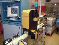
To meet this challenge for ILT, Image Labs International designed an automated inspection system to build on the classic vision-system approach, which relies on feature extraction and identification (see Fig. 1). This approach usually involves precision lighting control and exact definition of features such as perimeters, edges, flats, and holes. Sometimes defining this level of detail is not possible for a given product.
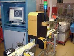
FIGURE 1. Automated inspection station, developed by Image Labs International for Integrated Liner Technologies, inspects special-purpose liners on bottle caps.
The new machine-vision inspection equipment has image-processing tools that rely on advanced algorithms in combination with the increasing power of computer systems. These tools allow the operator to program the system by loading images of “good” and “bad” parts, establishing an inspection standard. The system learns the important differences between these and also learns to ignore allowable variations.
As the product line grows and changes, the system incorporates additional product knowledge into an existing inspection system. For example, if a new defect is identified, possibly due to a new provider or process, images of the new “defect” can be captured and programmed into the classifier algorithm as “reject” parts. Similarly, if a change in process causes a new feature that the producer sees as acceptable, then images of the new feature can be captured and programmed into the classifier as “good” parts. In this manner, the system can learn and adapt to product and supplier variations.
System operation
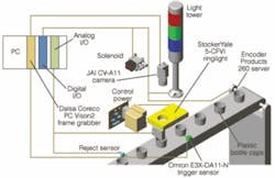
Bottle caps enter the system on a conveyor in a singe line and trigger an Omron E3X-DA11-N part-presence sensor when inside the inspection area (see Fig. 2). A StockerYale 5-CFVI ringlight in the housing gives a uniform view to the JAI CV-A11 progressive-scan, monochrome camera with a Fujinon HF25HA-1B lens with extension rings. The camera captures the image into the image-processing PC containing a Dalsa Coreco PCVision2 frame grabber. As the part proceeds down the conveyor, a Micro Epsilon Laser ILD1401-50 triangulation gauge also measures the height of the centerline of the cap. This tests the cap for double liners, something that is not visible otherwise in the image.
null
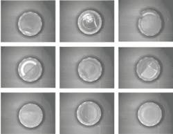
FIGURE 3. Images of cap liners are analyzed by an intelligent image classifier that has been trained with known-part samples. This algorithm classifies caps as “good” or “bad.” The image in the lower right is the only “good.”
Common Vision Blox software by Stemmer Imaging is then used to analyze the image with an intelligent image classifier that has been trained with known-part samples (see Fig. 3). This algorithm classifies items as “good” or “bad” (multiple categories are possible). The software also captures the height information from the laser sensor and makes a decision on single or double liner. These results are then combined into an overall part “pass” or “fail” result. When the part has moved down the conveyor away from the inspection area to the reject area. An air puff blows defective parts off the line into a reject bin for later study.
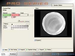
A computer interface allows the operator to control the sensitivity level of the system. Images are displayed in real time with annotations showing the areas with problems. A history of passed and rejected parts is displayed, so defect trends can be detected rapidly (see Fig. 4). Additional tables are used for configuring the system, creating reports, and diagnosing fault conditions.
System versatility allows this inspection technology to extend to other products. The basic criteria are the same for many different applications involving process control and other defect detection applications. This automated inspection station can be adapted to a number of general inspection tasks in various manufacturing environments.
Brian Smithgall is president and CEO of Image Labs International, Bozeman, MT, USA; www.imagelabs.com.
Company Info
Dalsa Coreco
St.-Laurent, QC, Canada
www.imaging.com
Encoder Products
Sagle, ID, USA
www.encoder.com
Fujinon
Wayne, NJ, USA
www.fujinon.com
Image Labs International
Bozeman, MT, USA
www.imagelabs.com
Integrated Liner Technologies
Albany, NY, USA
integratedliner.com
JAI
Glostrup, Denmark
www.jai.com
Micro Epsilon
Ortenburg, Germany
www.micro-epsilon.com
Stemmer Imaging
Puchheim, Germany
www.stemmer-imaging.de
Omron
Schaumburg, IL, USA
www.omron.com
StockerYale
Salem, NH, USA
www.stockeryale.com
