Vision system tests cell-phone displays
Multifunction station automatically tests LCD screen, along with backlight, speaker, clock battery, and magnet.
By C. G. Masi, Contributing Editor
Cell phones have evolved into compact units that pack a complex array of services into a very small package. Cell-phone manufacturers, therefore, have to test these functions rapidly, reliably, and at the lowest possible cost. To fulfill these requirements, a large electronics manufacturer contacted custom-production-equipment supplier Apna Technologies & Solutions, part of the Apna group of companies headquartered in Chennai, India, to create an automated functional test station to rapidly perform final inspection on its new cell-phone production line.
“They were setting up a new line with a higher production rate and had to replace their old final test process, which relied heavily on several manual test stations,” says Baskar Ceri, managing director at Apna. “It was only after we gave a quote on the job that they told us we’d have to deliver the system in 14 days.”
Test Requirements
The customer needed a final test station that would automatically functionally test the LCD screen, LCD backlight, speaker, real-time clock battery, and a magnet that is part of the system that senses when the cell phone’s flip top is closed. The company tests the magnet’s field strength with a Hall-effect sensor. The battery test is a simple voltage measurement, and the backlight is tested by switching a small resistance into the backlight’s power circuit to measure the current draw.
Speaker tests become more involved. To make sure the speaker voice coil is neither shorted nor open, its resistance is measured by running a controlled current through it and measuring the voltage across it. The speaker’s sound quality is measured by applying a multitone signal to it and listening with a microphone. The test program calculates total harmonic distortion in the received signal.
The LCD test is the most intricate. The test system applies various test patterns to the LCD, and a video camera observes the patterns appearing on the display. Finally, an image-analysis routine looks for presence/absence of individual pixels and lines, correct intensity, and image clarity. The display also includes built-in icons that can be switched on and off, so the system has to ensure that they are clear, properly shaped, and have sufficient contrast, as well.
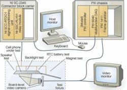
Figure 1. The cell-phone functional test system has three main components: a PXI chassis carrying the controller (host computer), a multifunction data-acquisition card, and a frame grabber that controls the station and provides most of the instrumentation. The second unit conditions the signals going to and from the PXI chassis. It consists of a connector block carrier that also includes a signal conditioning unit and a relay module. The third component is the test fixture, which contains the camera for testing the LCD, and other sensors to complete the rest of the tests. The user interface hardware includes the host computer’s monitor, along with a keyboard and mouse, and a video monitor to display a live feed from the video camera.
Apna developed a test system with three main elements: a test fixture and two instrumentation chassis (see Fig. 1). The main instrumentation set conforms to the PCI Extension for Instrumentation (PXI) standard and consists of a PXI-8184 controller that acts as the host computer for the system, a PXI 6040 multifunction data-acquisition module, and a PXI 1411 frame grabber plugged into a PXI-1002 mainframe chassis. Signal conditioning is done in a second chassis, which is a Model SC-2345 connector block carrier, containing an SCC-RTD01 signal-conditioning module and an SCC-RLY01 relay unit. All of these chassis and modules were manufactured by National Instruments (NI).
Most of the test signals originate or terminate in the multifunction module, but for simplicity of wiring, they are all routed through the signal-conditioning module. All of the multifunction board’s signals pass through a 68-conductor cable. The connector block carrier is designed to make wiring more convenient by accepting the cable through a 68-pin D-sub connector, then routing signals through signal-conditioning modules to a terminal block, from which they can easily be wired to the fixture. It also allows routing signals directly from the D-sub connector to the terminal block.
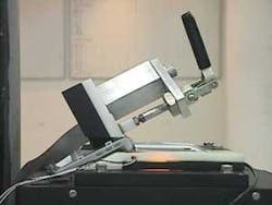
The test fixture provides routing for all signals to and from the unit under test (UUT) and carries a JAI Pulnix TMC-73M analog color camera (see photo, above). To minimize the test-fixture size, Apna engineers used a mirror to fold the optical path.
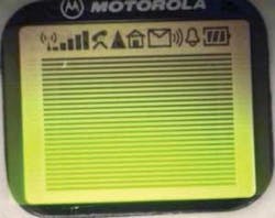
Unlike most optical inspection tasks, in this case the UUT provides all the illumination needed through its normal backlight, so the system tests the backlight before applying video test patterns to test the LCD (see Fig. 2). The test has to verify that pixels turn off and on, so the patterns can be generated simply by the multifunction board’s digital output pins. The patterns consist of icons built into the display toolbar area and a pattern of horizontal stripes covering the main display area. The icons are hard-wired into the display, so they can be turned on with just a single bit from the multifunction module’s digital output.
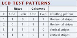
To test the rest of the display, however, individual pixels have to be turned off or on. The display works by addressing pixels individually by row and column. There are too many possibilities for the multifunction card’s digital I/O to address individually. Instead, the engineers designed a simpler test that needs only four bits: one bit addresses all the odd rows, another addresses all the even rows, a third addresses all the odd columns, and the fourth addresses all the even columns (see table).
null
Lock and Load
The test system runs automatically; the operator only places cell phones on the fixture, locks them in place, and takes them off again. The act of locking the unit into the fixture initiates the test sequence, which is controlled by an application written in NI TestStand test executive environment. TestStand calls individual test programs, written with NI LabVIEW test-programming environment, which perform the tasks. The vision-based tests use NI IMAQ vision software, which is integrated with LabVIEW.
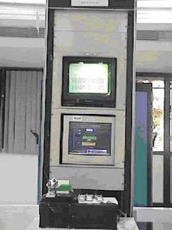
The test executive application steps through the sequence until either the UUT passes all of the tests, or it aborts at the first failure. After finishing the test sequence, the test executive archives the results on the controller’s hard disk and signals the operator to remove the UUT and sort it by whether it passed or not. The pass/fail information appears on a monitor directly over the test fixture (see Fig. 3). The station also feeds a live image from the camera to a second monitor mounted above the first.
The station software includes a report-generation module that provides reports of activity during each shift, tracking of faulty goods, station utilization factor, histograms showing how faulty units failed, and historical reports as needed by management.
Some tests can run simultaneously. For example, the signal-conditioning unit can be performing the magnet test while the multifunction module and frame grabber work together to test the LCD. Running these tests in parallel saves test time.
In the end, this new test station met all of the cell-phone manufacturer’s goals. It integrates all of the cell-phone functional tests in one fully automated system. At the same time, the architecture is flexible and open to allow modifications or incorporation of additional functions. It has proved to be highly reliable, running continuously through three shifts per day, six days per week. Most importantly, it reduced test time by a factor of three, requiring only 12 s to fully test each cell phone.
“And,” Ceri proudly reports, “we managed to beat the customer’s time table. We got the whole system built and installed in only 12 days.”
Company Info
Apna Technologies & Solutions
Bangalore, India
www.apnagroup.com/ats
National Instruments
Austin, TX, USA
www.ni.com
JAI Pulnix
San Jose, CA, USA
www.pulnix.com
