DSPs enhance image processing
By David Katz, Tomasz Lukasiak, and Rick Gentile
The Blackfin DSP family from Analog Devices is an example of these new high-performance embedded processors suitable for video and imaging applications. Along with a 600-MHz clock speed, the systems contain architectural enhancements that facilitate efficient data movement and processing. In addition, they provide a high-speed parallel-port interface that serves as a conduit for both video and analog/digital converter data.
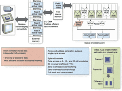
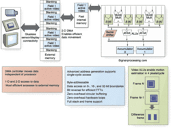
The memory hierarchy on the Blackfin processor includes various “levels” that trade off speed for capacity. The levels closest to the core processor are the fastest, but are typically too small to hold larger image buffers. This is one reason direct memory access (DMA) is so important. With DMA, data frameworks can move data into and out of the fastest memory, while larger buffers in off-chip memory are filled and sourced from video peripherals. DMA controllers operate independent of the core processor, and core cycles are expended only to service interrupts when transfers are complete. Each of the algorithms described below takes advantage of some type of DMA-based framework to achieve the best possible performance. These algorithms were selected because they find applicability in a wide cross-section of applications (see Fig. 1).
Convolution is one of the fundamental operations in image processing. In a two-dimensional convolution, the calculation performed for a given pixel is a weighted sum of intensity values from pixels in the neighborhood around that pixel. Since the neighborhood of a mask is centered on a given pixel, the mask usually has odd dimensions. The mask size is usually small relative to the image, and a 3 × 3 mask is a common choice, because it is computationally reasonable on a per-pixel basis, but large enough to detect edges in an image (see Fig. 2).
By aligning the input data properly, both Blackfin MAC units can be used in a single processor cycle to process two output points at a time. During this same cycle, multiple data fetches occur in parallel with the MAC operation. This method allows efficient computation of two output points for each loop iteration, or 4.5 cycles per pixel.
Edge Detection
A Sobel Detector uses two of these 3 × 3 convolution kernels to approximate both horizontal and vertical edges. The first matrix (Sx) detects changes in vertical contrast, while the second (Sy) detects changes in horizontal contrast.
The two output matrices hold an “edge likelihood” magnitude for each pixel in the image. These matrices are then thresholded to take advantage of the fact that large responses in magnitude correspond to edges within the image. If the true magnitude is not required for an application, this can save a costly square root operation. Other common techniques to build a threshold matrix include summing the gradients from each pixel or taking the largest of the two gradients, both of which will further improve performance. Using the technique that retains the larger of the two gradients on a 512 * 512-pixel image, it takes about 10 ms to process a frame on a 600-MHz dual-core Blackfin processor, using a two dimensional DMA-based data framework to move data in and results out of the fastest processor memory.
Straight-Line Detection
The Hough Transform is a widely used method for finding global patterns such as lines, circles, and ellipses in an image by localizing them in a parameterized space. Lines can be easily detected as points in Hough Transform space, based on the polar representation
ρ = x cos θ + y sin θ
One way to look at the Hough Transform is to consider a possible way that the algorithm could be implemented intuitively:
• Visit only white pixels in the binary image.
• For each pixel and everyθ value being considered, draw a line through the pixel at angle θ from the origin. Then calculate ρ, which is the length of the perpendicular between the origin and the line under consideration.
• Record this (ρ, θ) pair in an accumulation table.
• Repeat steps 1-3 for every white pixel in the image.
•Search the accumulation table for the (ρ, θ) pairs encountered most often. These pairs describe the most probable “lines” in the input image. This is because to register a high accumulation value, there had to be many white pixels that existed along the line described by the (ρ, θ) pair.
The Hough Transform is computationally intensive, because a sinusoid curve is calculated for each pixel in the input image. There are many ways to implement the transform. Sometimes, customizing it to a specific vision system is recommended.
Checking all pixels in an image to decide if they are to be considered for the Hough parameterization is very much a control-type operation. On the Blackfin processor, a predicted branch can take as little as one cycle, even though the processor has a 10-stage pipeline. This is impressive for a processor with signal-processing functionality, and it helps reduce the computation time in this case.
Computing the Hough parameters in floating point can be burdensome to a fixed-point machine. However, it has been shown that fixed-point Hough Transform calculation can perform very well compared to the full-blown floating-point implementations.1
Since the trigonometric functions in this equation can be precomputed and loaded at runtime, this opens up an opportunity to fully utilize the signal processing features of the Blackfin processor. Two multiplications can be performed in one cycle, along with two memory accesses, which are used to fetch the table values. In addition, a zero-overhead looping keeps the pipeline filled with instructions between each iteration.
The simplified Blackfin assembly code for the calculation ofρ looks like this:
cos_0 = cos[0] || sin_1 = sin[1]; // prefetch sin and cos values
lsetup(l_start, l_end) // loop over the θvalues
a0 = i * cos_0, a1 = j * sin_0 || cos1 = cos[1] || sin1 = sin[1];
// multiply the operands
a0 += a1; // add the results
...
l_end:
Sometimes, the Hough Transform map is smoothed with a low-pass filter to allow for more accurate localization of the peaks. This procedure can, of course, be performed with the convolution algorithm described earlier.
A Hough Transform implementation must be application-specific to be most efficient. For example, a requirement might be to detect the longest line in an image. For this type of application, it may be sufficient to search for the global maximum in the Hough space. Blackfin processors provide a vector MAX instruction that finds two maxima from two operand pairs. This can effectively cut the number of loop iterations needed to find a global maximum of a (Nρ× Nθ) Hough space to around (Nρ × Nθ)/2 cycles.
In addition to dual multiply-accumulate/arithmetic logic units (MAC/ALUs) for traditional signal-processing applications, Blackfin processors have four additional ALUs that can be used in a single-cycle instruction. These ALUs are very useful in an algorithm that involves motion estimation between image frames. The four ALUs can operate on four sets of bytes at a time. In addition, a quad 8-bit subtract-absolute-accumulate instruction subtracts four pairs of values, takes the absolute value of each difference, and accumulates each result into an accumulator.
Considering a 512 × 512-pixel image with 8-bit data, subtracting the corresponding bytes and accumulating the differences provides a quick way to see if an image has changed or if an object has moved within a frame. The benchmark is very straightforward--one core clock cycle is consumed for every 4 bytes of data processed-in this example, 262,144 pixels/4 pixels per cycle, or about 60 μs on a 600-MHz dual-core Blackfin processor.
The FFT is a fast algorithm for computing a discrete Fourier transform. When computed on 2-D data, its many uses include filtering via fast convolution, fast correlation, image enhancement, and object recognition. A 2-D FFT of anN × N image will also be of size N × N. The twiddle factors are usually computed prior to runtime. The Blackfin processors feature a bit-reversal option as well as a butterfly add/subtract instruction to accommodate efficient computation of FFT algorithms. To perform 2-D bit reversal, the N × N input image is stretched to a 1-D vector of size N2, because the transposed matrix formed out of the bit-reversed 1-D vector is equivalent to 2-D bit reversal.
Based on readily available code, the number of cycles required to compute a 16 × 16 complex 2-D FFT is 3816, including overhead. This code can actually be used to calculate a real FFT by setting the imaginary parts of the input array elements to zero. For a more efficient real FFT implementation using complex FFT code, two real-valued matrices can be packed as one complex input of a complex 2D FFT. This method, called “pack and split” or “mass production”, requires post-processing to separate the FFT output, and it requires two images to be transformed. This is normally not a problem in fast convolution or correlation, because two FFT transforms need to be computed anyway.21. G. Olmo and E. Magli, Proc. Int’l Conf. on Image Processing 3, p. 338 (2001).
2. W. Press et al., Numerical Recipes in C: The Art of Scientific Computing 2nd Ed., Chapter 12, Cambridge University Press, New York (1999).


