Component Integration: Integrating spheres calibrate sensors
Volume production of calibrated smart cameras with wide dynamic range requires fast, low-cost test-system and novel component design.
By Joe Jablonski, Chris Durell, Bruce Schulman, and Kelly Clifford
Forecasting the need for volume production of calibrated smart cameras, VICI Development worked with SphereOptics Hoffman to develop a fast, low-cost calibration test system that achieves the performance needed to support large-volume camera production. For its new OEM smart camera, VICI needed to provide a real-time self-correction platform for a wide-dynamic-range CMOS sensor array. Developing this calibration capability also enabled VICI to include other functions in the smart camera.
The need for per-pixel calibration capability is driven by the need to eliminate noise sources from the CMOS sensor images. Fixed-pattern noise sources can exceed other noise sources and limit image quality, especially in low-light and wide-dynamic-range scenes. Per-pixel image calibration corrections can attenuate fixed-pattern noise sources but involve computationally intense algorithms and also significant storage costs-multiple bytes per pixel.
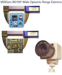
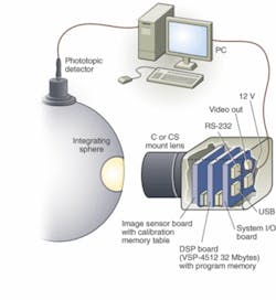
In the past, these calibrations have been applied as postprocessing algorithms within image workstations. VICI developed a low-cost, low-power image-processing board for the camera that enables a software-only image-processing pipeline capable of real-time sequential video functions. For example, the camera can compute per-pixel calibration, image processing, and compression within a small form factor targeting security and embedded imaging systems (see Fig. 1).
The VICI real-time correction processing uses on-board DSP techniques to decompress the calibration tables and implements the corrections on a per-pixel basis. VICI is also developing calibration firmware that collects the calibration data tables and computes correction tables to be stored with the sensor board for high-speed production self-testing.
INTEGRATING SPHERES
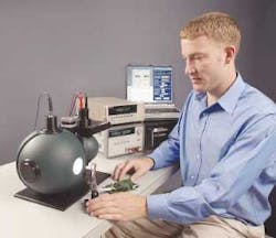
The calibration system is based on integrating spheres, which are a fundamental tool for the characterization of digital cameras, focal plane arrays (both CCD and CMOS), and sensor tests because of their unique ability to render a very uniform field of traceable luminance or radiance (see photo on p. 25). Properly designed sphere systems deliver a spatially (x, y) and angularly (Θ, Φ) uniform field to >98% of the sensor area and over a very-large-aperture area (<1 in. to >1 m) and large field of view (generally >90ofull angle). This field also can be varied in level over a very large dynamic range-seven decades of illumination, equivalent to a 24-bit ADC image sensor-by modulating the light input and without shifting the spectral radiance distribution.The integrating sphere provides a uniform calibrated light level across the output port at a known color temperature. The light level can be easily adjusted using variable apertures at the light source input port. A sensitive photoptic sensor standardizes the output-port light level. The output-port light level is extremely uniform because of the symmetry of the sphere and the dispersive nature of the coating on the inside of the sphere.
Additionally, an integrating sphere can be embedded with single or multiple monitoring solutions that allow the user real-time traceable feedback on the true levels of the sphere’s output (spectral, luminance, correlated color temperature, or filtered band monitoring). While there are some minor drawbacks to using integrating spheres, such as crosstalk between pixels, the variety and modularity of the features in an integrating sphere combine to make it a customizable primary calibration source for laboratory and production testing.
SPHERE SYSTEM
Several primary design features of the sphere-based calibration system required consideration for this project:
Sphere size, uniformity, size of aperture:Spheres are nominally capable of uniformity in excess of 98% and regularly exceed this requirement. To enable this performance, as a general rule, the sphere port size should be held to less than one-third of the sphere diameter. The camera aperture in this case was less than 2 in., which would dictate a 6-in. sphere. VICI and SphereOptics chose a higher-performance option to go to an oversized sphere and port of 12 in. and 4 in., respectively. The reason for this is that in the central 90% (or smaller diameter) of the port area, sphere irradiance/radiance uniformity can exceed 99%. The oversized port also allows a greater freedom in camera placement and angular presentation, with no reduction in performance. Since the light levels in this case were also relatively low, light-output reduction-which normally features significantly in the choice of a larger sphere (throughput follows the diameter squared)-was not much of a consideration
Nominal light level(s):VICI had three testing requirements-near the camera’s noise level (0.001 lux at exit port), at nominal luminance level (0.1-10 lux), and near its saturation level (10,000 lux). To address these three separate requirements, SphereOptics selected a second satellite sphere with a 20-W quartz tungsten halogen internally mounted light source. The satellite gives a low-level, controllable input to the main sphere; however, the satellite sphere source input cannot obtain the higher levels for saturation testing. So in this case, the internal source can be decoupled from the satellite sphere and brought directly to the main 12-in. sphere. This dynamic and flexible solution eliminated the need for multiple light sources and substantially cut cost to VICI.
Variability and dynamic range of light levels:VICI initially required three noncontinuous settings for testing spanning a dynamic range of 0.001 to 10,000 lux (>16 bits of range). However, SphereOptics used a filter holder between the satellite sphere and main sphere to allow VICI to use apertures and change the light level entering the main sphere. This permitted them to make their own apertures and inexpensively change the levels to meet their needs. In a production-oriented system designed for this application, VICI opted for a more-expensive 10,000-step automated variable attenuator (iris) to facilitate a series of very rapid light level settings. These apertures are also color/radiance neutral so spectral distribution (color temperature) is not affected by level changes.
Spectral radiance: VICI sought a source that had most of its energy distribution in the visible and near-infrared. Quartz tungsten halogen light sources provide a color temperature of 2970 K.
Performance monitoring:There are many ways to monitor the output of the sphere source level, including visible (photopic) detectors and spectral or other broad or narrow-band alternatives. VICI required a simple photopic detector to correlate to the illuminance levels at the exit port, so, with NIST traceability, SphereOptics calibrated this detector for lux (lumens/m2) at the port. This detector is read via a picoammeter to ensure maximum signal at the lowest levels of the sphere output. The output of this detector is real-time so the user can see any changes occurring to the system.
Data accessibility (electronics interface):The power supply and picoammeter for this system are both enabled for IEEE 488 or RS-232 communications, and VICI can access data from either unit through these data interfaces.
CALIBRATION AND AUTOMATION
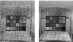
The sensor array consists of 640 × 480 pixels (VGA resolution). Because of the challenges in manufacturing these pixels in CMOS, there is a wide process variation of a number of parameters associated with each pixel (see Fig. 2). VICI’s approach to calibrating the pixels is to apply a known incident light level and then individually calibrate each pixel to the ensemble average output. This is done at several calibration light levels and the results are stored in memory. The calibration steps are: warm up the integrating sphere lamp; set the known incident light level that is uniform across the image array; compute an ensemble average of the pixel outputs over the array; compute a correction for each pixel to the ensemble average; repeat for each calibration light level; compute the compressed table of correction values; and store table in sensor memory.
With minimal user intervention, the camera’s DSP board processes all the required data from the sensor along with user-entered data from the photopic detector and computes its correction tables. The SphereOptics shutter control and data collection from the photopic detector will be automated in the future and will transmit data to the camera’s DSP board for a completely automated self-calibration for production. VICI forecasts that the test time during volume production will be less than 1 minute of integrating-sphere time per camera (see Fig. 3).
null
VIDEO PROCESSING
There is additional processing necessary to extend the dynamic range for each image capture to greater than 100 dB. Current commercial cameras typically operate over a 48-dB range in a single image and use multiple images in combination to achieve extended dynamic range. The implemented single-frame approach captures the images at video frame rate while multiframe approaches divide the usable frame rate from a video sensor by the number of frames required to achieve the same result.
Following the dynamic-range-enhancement image processing, additional processing steps are required to map the captured image into a range that can display on a TV or PC monitor. Both displays can typically accommodate a 48-dB intensity range. Each image-processing step has a range of user-controlled parameters that can be updated and stored in the camera.
The VICI camera is based on a ChipWrights 32-bit RISC-based visual signal processor (VSP4512) with an eight-way vector engine. This processor provides greater than 6000 MIPS for image-processing operations, computing the following functions at 30 frames/s on a 720 × 480-pixel image frame with 10 or 12 bits/pixel (>10 Mpixels/s): image calibration-per-pixel multivariable function =f[x, y, intensity, temperature]; min/max stretch; histogram calculation; histogram equalization; gamma correction; and color space mapping for NTSC/PAL output.
Because the image pipeline is in software, there is flexibility for each function. Users can fine-tune parameters from a hand-held terminal or PC. If an ASIC implementation were used for the high-speed image pipeline, VICI would need a new chip for each update of the processing algorithm. The VICI approach allows firmware upgrades in the field-download a new flash image and the entire image pipeline can be updated. The remaining processor bandwidth can be used for other image-processing functions.ChipWrights,Waltham, MA, USAwww.chipwrights.com
SphereOptics-Hoffman, Contoocook, NH, USA
www.sphereoptics.com
Vici Development, Las Vegas, NV, USA
www.vicidevelopment.com
