VME multiprocessors allow sonar systems TO DETECT SUBMARINES
VME multiprocessors allow sonar systems TO DETECT SUBMARINES
By Rick Nelson, Contributing Editor
The military`s embrace of commercial off-the-shelf technology is appearing just in time to confront a threat of increasing international concern--the operation of hostile diesel-electric submarines near shore. Diesel-electric submarines are small and quiet, making them inherently difficult to detect, especially with passive sonar systems.
Detecting submarines in these circumstances involves deploying sono buoys that listen for underwater sound and, in the case of multistatic active sonar, generate acoustic pulses, or pings. Each sonobuoy transmits its data to a central on-shore, shipboard, or airborne processing system that derives information from these data and presents it for operator interpretation.
In active sonar systems, ping sources and sensors are in different locations, neither of which is in the immediate vicinity of the target. Because the energy reflected from the target is highly directive, the location and aspect of the target relative to the source and sensor locations determine which available sensor will provide data most relevant to target detection.Targets act like mirrors, and, just as a light`s angle of reflection depends on the angle of incidence, sonar targets return echos that are strongest depending on the incidence angle (insonification angle) of the original signal.
Needle in a haystack
Jude Nitsche, vice president of BBN Systems and Technologies (Arlington, VA), likens the detection of a quiet submerged target to searching for a needle in a haystack. The haystack in antisubmarine warfare comprises the acoustic properties of targets and surroundings; the number, location, and types of sonobuoys deployed; and the availability of passive and active processing modes.
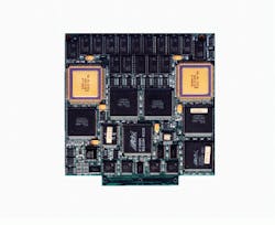
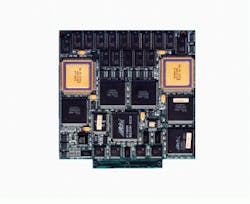
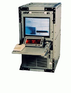
For a computer system to process and display multiple sonar inputs it must process multiple channels of one-dimensional data very quickly. In the design of the AAP-400 series of sonar processing and display systems, BBN Systems and Technologies chose a VME system based on a multiprocessing VME board from Sky Computers (Chelmsford, MA). To process multiple signals, the system first digitizes the analog signals. These signals are then distributed across multiple Sky i860-based SKYbolt processors. The AAP-400 includes a 20-slot multimission system and a portable suitcase-sized model with an integral flat-panel display (see Fig. 1).
Intelligent signal processing
Distributed multiprocessor system architectures such as the signal-processing engine (SPE) in the AP-400 require writing software that is efficient and maintainable. Although high system throughputs have been achieved with machine-specific code, developers at BBN configured software for the AAP-400 using scripts to determine the order of processing and to assign tasks to individual processors.
Processing is data-driven rather than tightly scheduled--individual processing functions occur only when enough data have accumulated in the input buffer to cause the processing to occur. This allows signal-processing tasks to be reconfigurable. Operators can specify where processing will occur and where the inputs are obtained for a given function.
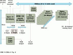
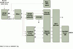
SPE software consists of two elements. A distributed-data-flow executive provides run-time configuration of the multiprocessor hardware, assigns processing software modules to specific hardware processors, transports data between the various software modules, and schedules real-time processing for execution (see Fig. 2).
The second SPE element is a library of I/O and signal-processing software modules. Currently, the SPE library contains modules implementing many signal-processing operations used for active and passive sonar processing, including modules for data input and output, adaptive beam forming, filtering, correlation, spectral analysis with noise equalization, normalization, automated signal screening, and real-time display formatting. New processing operations are implemented by adding C-coded modules to this library.
Data display
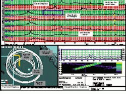
After the data are analyzed, they are displayed in three windows on the 19-in. monitor. Figure 3 shows the three-window display presented to the systems operator, including A-traces that give the amplitude (or intensity) of sound as a function of time for every sensor.
The tactical display (bottom left) gives a plain view of the sensors, sources, previously detected target locations, directional sensor bearing fixes, and multiple detection ellipses, overlaid on a bathymetric contour background. Multiple detection ellipses are generated from analysis of the A-trace data. The area where the ellipses cross indicates the probable location of a target.
A classification display (bottom right) magnifies selected A-trace regions and allows the operator to apply passive processing tools (both continuous narrow-band and intermittent), neural-net-based signal classifiers, special sensor processing capabilities, and environmental measurement tools to the data.
Creating a sonar database
A mission database is created on the system disk whenever the system is run in data-collection mode. This database stores the setup parameters, A-scan data, and tactical displays organized by acoustic event (ping number). Each detection also stores a five-second-long raw-data segment--known as a snippet--centered on the detection. The data-storage area on the system disk stores all events triggered over a six-hour period for 32 channels of processed data and an additional ten sensor hours of data snippets. The system disk and an 8-Gbyte DAT tape drive are packaged in the same canister and can archive the current mission or restore previously collected missions for further analysis.
Raw data streams are spooled to a 60-minute raw-data spool, and all channels are available for aural recall and snippet archiving at any time within an hour of the data occurrence. Two operator-selected channels of the real-time spool are continuously piped to a digital-to-analog converter that drives the aural monitoring subsystem. Replica correlation is performed on two or more broadband spectral replicas, and output data are integrated and overlapped before display in A-scan format.
The AAP-400 supports active and passive processing, multiple sensor display, signal archiving, replay of aural data, integrated tactical display, source and sensor field reconstruction, and echo classification.
More than ten AAP-400s are being used in laboratory and at-sea applications. These currently use from two to 12 Intel i860 processors, depending upon the needs of the application. This flexibility depends on the scalability of commercial off-the-shelf components such as the SKYbolt system.
Further Reading
E. S. Stickels et al., "Real Time Multi-Static Sonar Processing," published by Sky Computers Inc. (Chelmsford, MA).
J. R. Nitsche, E. S. Stickels, P. Brewer, and R. Mosten Rockwell, "Airborne Sonar for the Littoral."
Figure 1. Packaged in a flight-certified, roll-on/roll-off workstation weighing 430 lb, the sonar processing system is designed for airborne applications but has been used with towed-array and stationary-line-array sonar systems on surface ships and shore-based installations. The system uses the SKYbolt i860-based VME boards and Shamrock II daughtercards (top, right).
Figure 2 . BBN`s sonar processor is a multiprocessor VMEbus configuration that uses DMA transfers via the VME bus, the VSB (VME Subsystem Bus), or shared memory for interprocessor communication. A sigma-delta analog-to-digital converter minimizes the need for antialias filtering.
Figure 3. A-traces (top) show intensity of sound as a function of time for every sensor. The tactical display (bottom, left) shows a plan view of the sensors, sources, previously detected target locations, directional sensor bearing fixes, and multiple detection ellipses, overlaid on a bathymetric contour background. A classification display (bottom right) magnifies selected A-trace regions and allows the operator to apply passive processing tools to the data.
DIFAR eliminates target ambiguities
Directional bearings from directional frequency analysis and ranging (DIFAR) capable sensors eliminate positional ambiguities, allowing a sonar processing system to operate with few sensors. In operation, the AAP-400 from BBN Systems and Technologies (Arlington, VA) processes 32 DIFAR channels of acoustic data from sonobuoys deployed on the ocean surface in real time.
DIFAR sonobuoys provide directional and ranging information, multiplexed on an RF transmission to the maritime patrol aircraft carrying the AAP-400.The real-time processing chain includes antialias filtering/ADC, DIFAR demultiplexing, raw-data spooling, and automated signal screening and display.
The AAP-400 includes an integrated digital DIFAR demultiplexer to separate each sonobuoy`s omnidirectional (O) and north/south and east/west (NSEW) signal from the multiplexed data stream received by the aircraft from the sonobuoy.
