Scanner converts film to high-resolution digital images
Scanner converts film to high-resolution digital images
By Alan Richards
Geographic information systems (GISs), photogrammetry, and intelligence/reconnaissance applications require digitizing aerial photography at high resolution. The creation of high-accuracy digital maps is a relatively new application for image processing, because, historically, these applications have been limited by scan time, availability of storage, and complexity of input devices. Now, by using an off-the-shelf CCD camera and PC-based pipelined processor, Vexcel Imaging (Boulder, CO) has developed a scanner capable of imaging 9 ¥ 9-in. rolls of film or negatives at up to 7.5-µm/pixel resolution.
To digitize an aerial photograph, the system uses a CCD camera from Pulnix (Sunnyvale, CA) and PC-based image-processing hardware and software to apply geometric and radiometric correction. In operation, parts of the image (or tiles) are imaged at high resolution and then composed or "stitched" together digitally. The resulting images are then used in reconnaissance, construction, mapmaking, and environmental monitoring to plan, measure, and analyze the geographic data on the images.
Acquiring the image
Aerial photographs are provided to the scanner as 9 ¥ 9-in. images on film. These can be in sheets or continuous rolls. Depending on the level of detail in the original photograph and on the accuracy needs of the intended mapping/surveillance application, the field of view can be quickly adjusted to digitize each picture element from 7.5 to 120 µm of linear distance on the film. The variation is made by zooming the camera and adjusting the lens optics.
In a typical application, 15-µm-per-pixel resolution is achieved by focusing the 1 k ¥ 1 k array on a 0.6 ¥ 0.6-in. area. Thus, a 9 ¥ 9-in. photograph is imaged as 289 tiles, (17 ¥ 17 area of interest). This requires processing almost 300 million pixels per image.
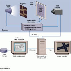
Acquiring a tile from the 9 ¥ 9-in. image is a two-step process. First, a tile of the target image is acquired through a glass plate etched with a precise grid (see Fig. 1). Because the film is back lit, only the image is captured. After this, the backlight is turned off, and the plate is side lit and imaged separately. The known coordinates of the grid in relation to pixel image data are used by the image processor as a reference point in reassembling the tiles and geometrically correcting the image. Intentionally faint, the reference grid presents a particular challenge in imaging the glass itself and finding the grid, but maximizes the quality of the digitized data.
Reassembling the image
To keep cost low and maximize customers` peripherals, software, and upgrade options, the image-processing system in the scanner is based on a Pentium Pro-PCI CPU board running at 200 MHz. At the heart of the image-processing system is the MVC 150/40-PCI board from Imaging Technology (ITI; Woburn, MA), a PCI board that is the foundation of a pipeline image-processing subsystem. The MVC 150/40-PCI includes the timing and controls for a separate 40-MHz image pipeline, primary image memory, a cross-port switch for the image pipeline, the interface to the host CPU, a slot for a camera interface, and another slot for a pipeline processing daughter module.
The MVC 150/40 system is based on a 40-MHz video bus that connects all the elements in the pipeline and a cross-port switch that supports four channels, each of 40 Mpixels/s. The pipeline architecture, the 40-MHz clock rate, and specialized processors are key to meeting the performance needs of the GIS application.
The two daughter slots on the PC motherboard include an acquisition module that provides interface and control for the 1 k x 1 k camera and a CM-GEO--a computational module for geometric remapping. The scanner also uses Imaging Technology`s CM-CLU, a computational module convolver/arithmetic logic unit that is located on the same 40-MHz pixel pipeline but that sits physically on the 150/40 system expansion motherboard.
Warping the images
To perform real-time geometric remapping or "warping" of the digital images, the scanner uses the CM-GEO module. As an addition to the 150/40 pipeline, this hardware engine includes discrete processors for address generation (x and y), a look-up table (LUT) for interpolation coefficients, a bilinear interpolator, and memory.
In processing the image data, geometric correction is used to adjust for small errors in camera position and angle, and radiometric correction is used to normalize brightness across the image. One of the key difficulties is recognizing where the reference grid is located, because the acquired grid image is always of low brightness and low contrast. The task involves recognizing the fine grid lines, computing the centers of the horizontal and vertical lines, and determining a transform between the image and the CCD pixels. These transform coordinates are subsequently used in a resampling operation to map the original pixels digitized in CCD space to new pixels calculated in grid space. This mapping is performed by bilinear interpolation algorithms on the CM-GEO module. Once the geometric location of each pixel is determined, a gray value must be assigned. This is performed by floating-point bilinear transformations.
Recognizing grid lines
As a general-purpose pipeline processor for convolutions, edge detection, and calculating image statistics, the primary function of the CM-CLU is an edge-detection (convolution) operation that steps a kernel across the image of the glass to recognize grid lines. The input stage of the CM-CLU includes LUTs and a 40-MHz, 4 ¥ 4 convolver that performs a 4 ¥ 4 operation on a 1 k ¥ 1 k image in 30 ms.
By automatically adjusting the size of the area of interest to eliminate unwanted data produced at the edges of convolved images, the CM-CLU saves processing time. The hardware also includes two 16-bit output LUTs that can be used to shift the image data any number of bit positions, to divide two images, or to scale 16-bit results to 8-bit data for display. In the scanner, the CM-CLU also performs convolution operations on the image tiles to enhance the image and correct for other artifacts of scanning.
Programs for the image processor were developed with Imaging Technology`s ITEX-VIP libraries. These contain optimized C functions for the pipeline hardware and eliminate the need to develop common image-processing algorithms such as edge detection. ITEX-VIP is ITI`s point-and-click GUI software tool, a compiler that generates optimized C code for the MVC 150/40 hardware. Output of the ITEX-VIP compiler was then interfaced to custom- developed, application-specific C code.
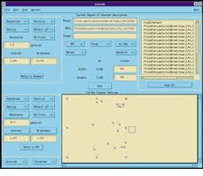
Under control of an X-windows-based user interface, different regions from the same image can be digitized (see Fig. 2). The operator uses the "live" camera view that is displayed on the image monitor to preview the effects of different settings before starting a scan. The user makes adjustments until the image displayed by the camera is acceptable and then transfers those settings to the desired ROI. With the pipeline processor, each image tile is processed in 2.5 s; an entire 289-tile image is processed in about 12 minutes. Other innovations made possible by advanced software and fast processing engines include calibration for gray balance and focus and shift correction.
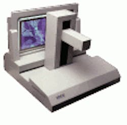
Developed for geographic information systems and intelligence applications, this film scanner performs rapid identification and acquisition of regions of interest from aerial photography.
Figure 1. Using the scanner, high resolution is achieved by focusing the camera array on a small part of the film (tile) to be imaged. By acquiring two images, one through a glass plate etched with a precise grid (upper right) and one without, coordinates of the grid in relation to pixel-image data can be used to reassemble the of film into a larger image.
Figure 2. Under control of an X-windows-based workstation, radiometric settings for different regions of interest (ROI) can be set. Radiometric settings for the currently active ROI are shown (upper left), while the active region of the image is shown as red in the bottom right corner. Radiometric settings (bottom, left) show the settings applied to the camera.


