Rugged system monitors steel-strip process
Linescan camera and off-the-shelf components withstand high temperatures and debris.
By David Wyatt
When Mittal Steel purchased a hot-strip steel mill in East Chicago, IN, USA, it got a hot-strip machine-vision inspection system, as well. The problem was that the inspection system was buried in a melted and twisted enclosure inside a pit underneath the conveyor that carries the strips from the furnace. Therefore, the company needed a new inspection and process-control system if it was to optimize production.
Mittal turned to Midwest Integration to update its vision system. Midwest constructed a system based on a Cognex Legend LS linescan CCD camera with on-board image processing interfaced to a custom Visual Basic .NET supervisory program running on a desktop PC. To handle the 2200°F conditions, the camera and PC are housed in a custom stainless-steel enclosure, with slit viewer for the camera. Forced air keeps debris away from the camera optics. An Omega microserver connected via Ethernet to the PC monitors the temperature and humidity inside the housing.
Steel-Strip Processing
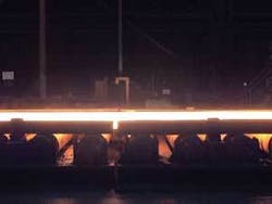
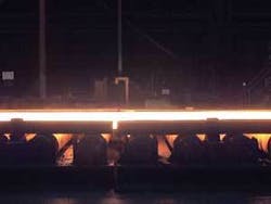
Steel-strip mills produce slabs measuring a few feet in width and up to hundreds of feet in length. The Mittal plant produces slabs 79 ft long from its furnaces (see Fig. 1). This application calls for finding defects as small as 0.5 × 0.5 in. at speeds of 250 ft/min. Defects include scratches, surface defects, tears, and cold spots. A tear appears as a hot spot because the inside of the slab is at a higher temperature than the surface coming out of the furnace. Scratches appear as cold spots, or darker sections of the image, due to a UV filter mounted on the linescan camera.
The slabs move along a powered skate conveyor located above the inspection station. The camera images the slab as it moves above it, so a linescan camera was more appropriate to create 79-ft images than an area-scan camera. The camera also has an Ethernet port, which makes it easy to transfer data back to the host PC, which is a standard desktop version running the fastest Intel processor available at the time-the Pentium IV Extreme at 3.6 GHz. Although most of the processing is done on the camera, the system needs high processing bandwidth and up to 2 Gbytes of RAM to display the large slab TIF files in real time. A separate Measurement Computing DAS 1002 A/D card inside the PC provides discrete I/O for triggering and other time-sensitive communication and camera controls, as well as collecting data from pyrometers that detect the slab and monitor the nearby temperature of the slab during inspection.
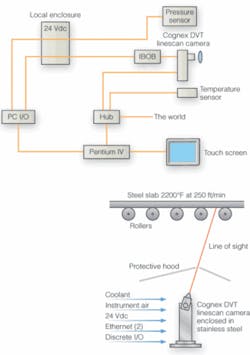
The operator initiates the system through a ruggedized industrial touch-screen panel from Elo Touch System, mounted on a nearby rack. The 2000-pixel linescan camera captures a single-row image of the steel slab as it passes overhead, viewing the slab through a small slit in the stainless-steel enclosure. The enclosure was built with air nozzles near the optics and inside the main enclosure to create positive pressure and keep debris from the steel-mill operations from fouling the system. A separate glycol circulator keeps the enclosure at a fairly constant temperature of 70°F, which is within the operating temperature of the camera and electronics. Finally, the camera section of the enclosure is connected with fast-release thumb screws to allow easy access to the optics in the event that an error condition occurs, such as a visual defect in the same location along the full length of the slab, which might indicate a fouled optic (see Fig. 2).
FIGURE 2. Linescan-camera-based system located below the conveyor belt is encased in a stainless-steel enclosure. Thumb screws are used to secure a separate cover over the camera and optics for easy access to the most commonly fouled parts in the hazardous steel manufacturing environment (left). Glycol and air hoses can be seen entering and exiting the machine-vision enclosure, which is mounted below the skate conveyors, looking upward (right).
An Omega Engineering microserver inside the enclosure with both temperature and humidity sensors transmits environmental data via Ethernet to the PC, which passes it to the Visual Basic .NET supervisory program for display on the operator’s touch screen. The full control panel and slab viewing program can be accessed from both the operator’s touch screen and the plant control pulpit via LAN or across the Internet with appropriate plant network access. If temperature values exceed preset limits, an alarm is sounded to check the enclosure; a humidity alarm means a possible glycol leak. A separate pressure sensor connected to the DAS1002 card in the PC lets the operator know if pressure levels inside the enclosure have dropped to unsafe levels, possibly as a result of a drop in the plant’s air-pressure supply lines (see Fig. 3).
Pyrometers mounted above and below the conveyor monitor the temperature and send the data through to the DAS1002 card. The data are stored on the local hard drive along with image data and product data from the plant network in a hierarchical tree structure on the PC’s hard drive. Increases in temperature above preset thresholds indicate the presence of a slab, and the VB.NET supervisory program uses that information to trigger the camera to start acquiring data.
Up to 8000 rows of image data are stored in the camera’s 128-Mbyte on-board RAM. The camera uses a dynamic gain-control filter based on the “brightness” of the last slab the system inspected. If the slab is too bright, it could block out defects because of insufficient contrast. This is most critical at the beginning and end of a slab because these sections vary the most from the norm. Then the camera performs standard binary morphology and blob analysis on the image data to locate defects and sends that information along with the image data across the Ethernet cable to the PC host.
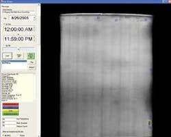
Each 79-ft slab requires three separate image files because of the memory limitations on the Legend camera. The VB.NET program takes the three images and stitches them together into a single slab image file. For each slab, the final image, slab data from the network, pyrometer data, and inspection-result data are saved in a directory for that day. The inspection software displays the slab image, slab data, and inspection results of the most recent inspection (see Fig. 4).
FIGURE 4.Visual Basic .NET supervisory program displays visual, temperature, and humidity data on a touch screen. A tear appears as a hot spot; scratches appear as cold spots or darker sections of the image.
At the host, VB.NET checks each incoming defects against defect parameters set by the operator through an error-configuration screen. The system only reports and displays the defects based on size, length, width, location, and other parameters set by the process engineers at the Mittal plant. VB.NET displays the slab image with highlighted credible defects. Each section of the slab with a defect is stored separately with textual information tags on the hard drive in the hierarchical file structure. The images are displayed as both images and searchable text tags (part of the hierarchical file storage) in the main VB.NET program.
A separate custom application reviews the previously saved slab images and inspection data. The program can call up images based on defect type, date, time, and other criteria important to helping the plant’s operators evaluate and correct the steel furnace and alloy mixes to produce the appropriate product. The separate reviewing program also allows an operator to view any previous inspection results, as long as they have access to the shared directory containing those results.
The inspection system is completely automatic, and its results are monitored by plant engineers to help them adjust their process. Process control in the steel industry is different from control in other industies. When a few hundred feet of burning steel is set in motion, there is not much that can be done to change it except to create alarm conditions from the inspection system to alert the engineer to a problem. The engineer may then to shut down the furnace and change the burner profiles to improve performance.
Mittal’s mill operator did have a second reason for installing the inspection system- qualifying the outgoing product for more aggressive pricing policies. Some customers require 100% defect-free steel coils, which is the end product from the slabs. Other customers do not require that level of purity. The steel-slab inspection system allows the mill operator to improve productivity by monitoring the furnaces in real time, while 100% vision inspection and archiving allow the mill operator to sell steel that might have been reworked and thus increase productivity.
David Wyattis president, Midwest Integration, Mishawaka, IN, USA; www.midvision.com.
null
