Galileo spacecraft images
Galileo spacecraft images
By John Haystead, Contributing Editor
OWhile accurate mapping and atmospheric velocity measurements demanded a camera with excellent geometric fidelity,O says Klaasen, Oprecise photometric measurements demanded a stable linear detector that could be calibrated remotely.O Because both atmospheric motion and geologic formations needed to be studied, a camera with a large field of view (FOV) was used.
CCD-based imaging
Galileo?s SSI design was constrained by a number of factors including available telemetry rate, potential image smearing caused by spacecraft motion, and the radiation shielding needed to protect the camera from Jupiter?s harsh environment. The virtual-phase CCD imaging array was built by Texas Instruments (Dallas, TX) and JPL. The frontside-illuminated array is surrounded by a 1-cm-thick tantalum radiation shield to protect it from the high-energy particle irradiation of Jupiter?s magnetosphere.
To observe Jupiter?s auroras, lightning storms, and rings required a detector of high sensitivity and an optical system capable of rejecting scattered light. Out of several thousand attempts to produce a detector array suitable for the mission, only two detectors of flight quality were made. Originally, a thinned three-phase detector was planned, but this was abandoned because applied voltages could not be adequately controlled under irradiation by high-energy particles.
Because the high levels of neutrons emitted by Galileo?s on-board power sources could degrade image quality, the camera?s CCD is cooled to 163 K (?166?F). While transient radiation-induced effects occur when the spacecraft is near Jupiter, no significant damage is expected up to a total radiation dose of 1000 J/kg (100,000 rad).
According to Klaasen, pixels that are damaged are treated as unusable. But to date, only a few hundred pixels of the 640k picture elements have been
affected. According to Belton, this is not a problem because a certain amount of CCD pixel damage due to charged particles was expected. OOnly very-long-exposure images and images taken deep within the radiation belt are affected.
Space-age systems
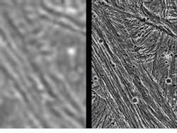
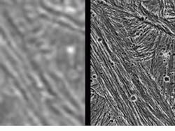
Designed and assembled at JPL, Galileo?s imaging system comprises a telescope, image sensor, filter wheel, focal-plane shutter, and associated electronics. Although Galileo carries the same 59-in.-focal-length telescope as the Voyager spacecraft, its spectral range and resolution is greater than Voyager?s, operating farther into the infrared (IR) spectrum (see Fig. 1). Its FOV is 8.13 8.13 mrad, with a resolution of 34 line pairs per mm and 28 exposure times that range between 0.004 and 51.2 s.
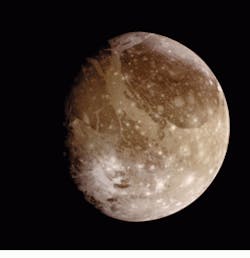
To study the composition of Jupiter, its atmosphere and moons, the SSI uses seven spectral filters operating from 400 to 1100 nm and a Oclear? filter. Because the SSI can capture visible and near-IR frequencies, composition of the planet?s surface material can be studied. The SSI?s near-IR filters allow the SSI to image different atmospheric levels and the color and morphology of surface features. Color images are generated by taking multiple images of the same scene using the eight-position filter wheel (see Fig. 2). These images are then combined at a ground-based image laboratory.
JPL supports the Galileo spacecraft by continuously evaluating camera performance to ensure that parameters such as exposure times, data compression, and editing are operational. It also conducts ongoing calibration of the spacecraft?s instruments and evaluates radiation noise levels. While Galileo was traveling to Jupiter, JPL evaluated shutter performance, pixel by pixel response, gain ratio settings, radiation response, spatial resolution performance, scattered light performance, and noise levels of the camera.
Unlike many image-processing applications, data throughput was never a problem. Because Galileo lost its main high-gain antenna early in the mission, the total number of images taken and subsequent image processing required was reduced by more than a factor of 10. Data rates from Galileo?s remaining low-gain omnidirectional antenna range from 20 to 160 bits/s.
According to Bill Green, manager of the Science Data Processing System Section at JPL, this created different challenges, because most images are transmitted as multiple image fragments that must be reassembled into complete images. Fragments are received at a number of different telemetry groundstations around the globe and are sent to the Multimission Image Processing System (MIPS) over long periods of time.
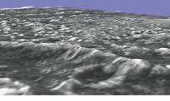
ODepending on the atmospheric conditions at the various receiving stations, quality of data that can be received can vary significantly. We need to sort through all the data from all the stations and select the best-quality version of each fragment for use in reconstructing standard and stereoscopic images,O says Green (see Fig. 3). Most of this selection and sorting is performed automatically using quality-factor algorithms running on Alpha workstations.
Piecing images together
Image quality from the spaceborne telescope is enhanced using the digital image-processing capabilities of JPL?s ground-based image-reconstruction computers. Raw satellite data captured at NASA?s deep-space-network ground stations are routed to JPL?s Multimission Image Processing System Laboratory over satellite and ground lines.
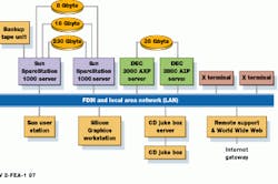
In operation, data from Galileo are transmitted over JPL?s local-area network to two 3800 Alpha workstations from Digital Equipment Corp. (Maynard, MA) that perform image decoding, sorting, and error correction. Data are then transferred to two Sun Microsystems (Mountain View, CA) UNIX SPARC 1000 workstations that serve as data servers for the Galileo science and image-reconstruction teams located worldwide (see Fig. 4). A catalog of each image?s attributes is created and stored on the servers.
The MIPS facility operates video information cataloging and retrieval (VICAR) software and a number of commercially available software packages such as the In
Radiation-hardened CCD sensors coupled to on-board telemetry systems are providing images of Jupiter andits satellites.
FIGURE 1. Two images of Jupiter`s moon Ganymede show the relative resolution of Voyager 2 and Galileo spacecraft: image of Ganymede taken by the Voyager 2 spacecraft with a resolution of about 0.8 mile per pixel (left) and the same area captured by Galileo during its first flyby of Ganymede on June 27, 1996 (right). The image taken from Galileo has a resolution of 243 feet per pixel, more than 17 times better than the Voyager image.
FIGURE 2. Color view of Ganymede from the Galileo spacecraft has the sun illuminating the surface from the right. Dark areas are older, cratered regions while light areas are younger, tectonically deformed regions. The finest details that can be discerned are 13.4 km across.
FIGURE 3. Topographic detail of Jupiter`s moon Ganymede is shown in a computer reconstruction from two images taken by Galileo. One was taken June 27, 1996, at a range of 5685 miles. The other was taken at a range of 6350 miles on September 6. The topographic nature of the deep furrows and impact craters that cover this portion of Ganymede is apparent. The blue-sky horizon is artificial.
Image compression speeds data transfer
To speed image-data transfer from the Galileo spacecraft to receiving stations on Earth, two types of image compression were used. Integer Cosine Transform (ICT) compression operates on 8 ¥ 8-pixel blocks with data encoded as 8 bits/pixel. Galileo`s operators typically apply ICT compression factors between approximately 5 and 15 to 1. With a typical compression ratio of 10 to 1, an 800 ¥ 800 image at 40 bits/s requires approximately 3.5 hours to transmit.
While ICT delivers high compression ratios, it is also inherently lossy, leading to blocky high-contrast images. For this reason, ICT compression is not used for all data, some of which are encoded by Block Adaptive Rate Controlled (BARC) compression. BARC compression provides a ratio of 2.54 to 1 and can be either lossless or lossy.
Because Galileo flies around Jupiter in an elliptical orbit, there are only a few days when it is close enough for image acquisition. During these times, data are recorded on tape and then transmitted back to earth, providing images at a rate of two to three images per day.
FIGURE 4. Multiple workstations, linked using a FDDI backbone comprise the image-processing facility at the Jet Propulsion Laboratory (JPL). After two Digital Equipment 3800 AXP workstations perform image decoding, sorting, and error correction, data are transferred to two UNIX SPARC 1000 workstations for image archiving.
