PARALLEL PROCESSORS SPEED medical image reconstruction
PARALLEL PROCESSORS SPEED medical image reconstruction
By Lawrence H. Brown, Contributing Editor
In the last ten years, the time required to reconstruct three-dimensional (3-D) images from positron-emission-tomography (PET) scanners has decreased from six hours to nine minutes. One of the more significant developments in this area has been the Advanced Rotating Tomograph (ART) from CTI/Siemens (Knoxville, TN). Commercially available since 1994, the ART is based on the concepts of David Townsend (University of Pittsburgh, PA), who built the first of two prototypes in Geneva, Switzerland, in 1992. Townsend wanted to find ways of reducing the costs to make PET technology more accessible.
Unlike computed tomography or magnetic resonance imaging, which look at human anatomy, PET is used to study metabolic activity of the body. In particular, the modality can assess coronary-artery bypass surgery, identify causes of childhood seizures and adult dementia, and detect and grade tumors.
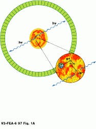
Before the PET procedure, patients are fed or injected with a radioisotope-based tracer. These isotopes then become distributed throughout the body and discharge positrons. As positrons encounter electrons in the body, the electron-proton pair is annihilated, emitting two 511-keV gamma rays in opposite directions. Both gamma rays impinge, almost simultaneously, upon bismuth germanate crystals in the circular gantry of the tomograph, producing photons. These photons are then detected by sensors, also located in the gantry. This simultaneous detection is referred to as a true coincidence, and the opposing data points are used to reconstruct 3-D data (see Fig. 1).
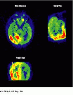
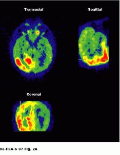
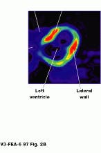
Because the radiopharmaceutical contains a chemical commonly used by the body, PET lets the physician see the location of metabolic processes. Glucose combined with a radioisotope, for example, will show where energy is being used in the brain, heart muscle, or a growing tumor (see Fig. 2).
Capturing radiation
To obtain the best sensitivity, PET scanners must be designed to capture as much emitted radiation as possible. To do so, multiring scanners cover an axial length of 10 ¥ 15 cm and, when operated in two dimensions, have a sensitivity of 0.5%-1%. This means that, at most, 1% of the radioactivity in the field of view of the scanner is used to construct PET images. With the widely used PET tracer 18-F deoxyglucose, only approximately 5% is absorbed by the brain, and only 0.05% contributes to any recorded image.
Because the human body emits radiation in three dimensions, operating a PET scanner in two dimensions makes poor use of the available photon flux. However, until 1991, this was the standard mode of acquisition because 3-D reconstruction algorithms were not well developed. Worse, the thin lead shields used to reduce the amount of scatter between detectors in early PET scanners contributed to loss of sensitivity. Retracting these lead shields requires 3-D reconstruction algorithms and more accurate scatter correction techniques.
When operated with lead shields retracted, multiring PET scanners have an absolute sensitivity of 3%-4.5%. Although retracting the lead shields increases the amount of data collection by five, the twofold increase in scatter (15% to 30%), and the tenfold increase in data for each scan (from 5 to 50 Mbyte) requires parallelization and 3-D reconstruction techniques.
The development of the appropriate 3-D reconstruction algorithms and methods to correct for the increase in scattered radiation has led to the development of 3-D PET scanners. In such systems, patient images can be acquired faster with lower radioactive doses. Alternatively, images with much greater detail can be obtained in reasonable time frames.
The greatest expense in PET technology has always been the detectors that record gamma events. To reduce the costs, Townsend and his colleagues redesigned the detector ring as two banks of detectors that rotate as the patient moves through the gantry. Each detector is divided into crystal blocks--an 8 ¥ 8 matrix of 64 elements that face the patient. "This design reduces the total number of detectors by one-half over the previous design," says Townsend.
Processing power
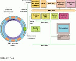
All detector and coincidence detection circuits located in the tomograph gantry are ASICs, including an analog/mixed-signal front-end IC with nine A/D converters. A specialized ASIC, dubbed the coincidence processor, located with the detector banks on the rotating ring, processes more than 4 million events/second. Only true coincidence events--two gamma events occurring within a 12-ns interval at 180--are processed. Coincidence events are sent via an optical data link from the rotating ring to a set of stationary receivers and then via a four-foot coaxial cable to the system`s proprietary data formatter and motion translator (see Fig. 3).
Histogram data are then sent to another proprietary board where they are sorted with respect to the angular position of the gantry at the time of occurrence. These data are then sent over the VSB bus where they are stored in an off-the-shelf 64-Mbyte VME board from Chrislin Industries (Westlake Village, CA) before being written to an 8-Mbyte/s, 9.0-Gbyte drive from Seagate (Scotts Valley, CA).
To control the gantry of the PET scanner, the VME-based system uses an off-the-shelf 68040-based VME board from Force Computer (San Jose, CA). This real-time CPU sends commands to the gantry`s microcontroller through a serial port. A Sparc-2 CPU board transfers the collected data to a SuperCard4 board from CSPI (Billerica, MA), where 3-D reconstruction is performed. Because each i860 has 16 Mbytes of memory, reconstruction can be accomplished using a distributed-memory model. Scatter correction is performed in parallel as a model-base correction. Data-attenuation correction factors are applied to the collected data by the SPARC-2 CPU that also operates as the user interface and system controller.
To find a method of reconstructing data collected from 3-D (or volume) PET scanners into images posed unique challenges. For 2-D imaging, several reliable methods exist based on the Fourier transform. Alan Cormack won the Nobel prize for his work in applying these 2-D methods to x-ray CAT scanners.
Fourier-transform methods work for 2-D scanners because such scanners image a series of single image planes in an independent manner--the overall response of the scanner is independent of the location of objects inside the scanner and is said to be shift-invariant. Thus, the total activity seen by the scanner doesn`t change (is invariant) if an object`s position is shifted inside the scanner plane. To visualize this, imagine a point object inside a circle representing the scanner plane. Shifting the point object changes its location, but not the total signal seen by the scanner.
The shift-invariance of 2-D scanners allows developers to use optimized fast-Fourier-transform (FFT) methods for fast and reliable 2-D image reconstruction. However, 3-D PET imaging is not shift-invariant, but rather, shift-variant. For example, imagine a point object inside an open cylinder that represents a volume (3-D) scanner. In this case, shifting the point object changes the total signal received by the scanner.
The goal of the 3-D reprojection is to restore shift-invariance to scanner data and allow FFTs to be used in image reconstruction. To do so, the 2-D subset from the data that would have been collected by a 2-D scanner is first extracted. This subset is reconstructed into an initial estimate of the image. This estimate is accurate but very noisy, as only a small fraction of the data is used. From this first-pass estimate, the data that would have been collected by a much longer scanner are calculated by the process of reprojecting (similar to ray-tracing) through the first-pass image.
Although this results in a data set that is larger, it is shift-invariant. The new data set, which consists of all of the original and reprojected data, can now be reconstructed using FFT and 3-D ray-tracing methods. Although 3-D reprojection uses FFTs for image reconstruction, the computation in 3-D image reconstruction is orders of magnitude more than that required in 2-D reconstruction, due to the larger data set and the need to use 3-D ray-tracing methods. This increase in computational complexity has led to the implementation of the 3-D reprojection method on parallel processors in commercial 3-D PET scanners.
In the ART PET, reprojection software dubbed PROMIS--Projection of Missing Sinograms--is used to reconstruct images. This is a 3-D reconstruction algorithm designed for PET systems by Paul Kinahan of the University of Pittsburgh (Pittsburgh, PA) and Joel Rogers of TRIUMF (Vancouver, BC, Canada).
Current research aims to increase image signal-to-noise ratio and improve temporal resolution. Given the intrinsic 3-D nature of PET and the requirement for high sensitivity, 3-D scanning will become the standard mode of operation.
FIGURE 2. Image of the brain shows three different reconstructions. Epileptic activity is visible in red. (Photo, top, courtesy of CERN, Geneva, Switzerland) Cardiac PET images are normally obtained as a set of transverse cross-sectional images. In general, the heart and tomograph long axes deviate, producing oblique images (Photo courtesy of UCLA Medical Center; bottom).
FIGURE 1. Positrons emitted from the body during a PET scan interact with electrons, emitting two gamma rays that are detected by opposing banks of detectors (Illustration courtesy of CERN, Geneva, Switzerland).
FIGURE 3. Built around the VME-bus, the ART PET scanner processor uses a multiple i860-based processor from CSPI to perform image reconstruction.
Acknowledgement
The author would like to thank Dr. Paul Kinahan, University of Pittsburgh Medical Center 9pittsburgh, PA), for his help in preparing this article.
