Machine vision qualifies automotive applications
Schott Glass' Fiber Optics Division (Mainz, Germany) produces glass fibers that are used by its sister company Schott Fiber Optics (Doncaster, UK) in the manufacture of automotive lighting harnesses. To build these harnesses, four fiberoptic bundles are used to illuminate an annular ring of polycarbonate. All four bundles are illuminated by a single light source located in the rear of the headlamp assembly. During operation, each bundle must transmit equal illumination to its own quarter of the polycarbonate ring or else the overall lighting effect will be substandard.
Each bundle consists of around 3000 70-µm-diameter fibers sheathed in plastic, which makes up a 4.2-mm-diameter bundle. An eyelet is crimped on one end of each bundle, a few millimeters from the ends of the optical fibers. This design allows the later addition of a clear epoxy resin seal that provides the final termination and ensures the uniform emission of light to the polycarbonate ring.
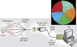
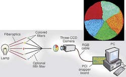
The four bundles are then placed in the frame of a custom-built assembly machine that trims the end of the four bundles with a rotating diamond blade. A common end ferrule is then placed over the four bundles and crimped tightly. While in the assembly machine, each bundle is illuminated separately by a Schott-developed filtered-light source that produces yellow, magenta, blue, or green light. Each of the four bundles transmits a single color. A DXC003P three-CCD camera from Sony (Park Ridge, NJ) captures the resultant color images with a 24-bit PCI-based Snapper frame grabber from DataCell (Finchampstead, Berkshire, England). This frame grabber captures an image of the four colors as they are emitted at the end of the lighting assembly.
In automated automotive-lighting-assembly inspection system, an off-the-shelf camera images groups of fiber bundles to determine light intensities.
An Intel Pentium PCI-based PC processes the captured data. Not only must the optical fibers from each bundle remain in their own quadrant, but each quadrant must also transmit an equivalent amount of light across the whole cross section of optical fibers. A mathematical algorithm developed using Microsoft C++ and WIT from Coreco Imaging (Billerica, MA) breaks down each quadrant into concentric annular sectors and compares the light intensities from all four sources.
"The way the fiber bundles are manufactured means that there will be the same amount of each color present," says Tim Fletcher, DataCell business manager of defense and industrial imaging. "There is more light transmitted by the core of the tail than the edge, so the application divides the image into annular rings. The percentage of each color existing within this ring is then calculated. The center is more highly weighted than the periphery, and Schott has a formula that produces a pass/fail decision based on the outcome of each colored segment," he adds.
If the decision indicates a failure, then the PC signals a PLC using a PCDIO16 PCI-based digital I/O board from National Instruments (Austin, TX) to reject the part. Data are captured by the system so that the failing part can be examined, at a later time, alongside data indicating the reason for the fault.
Finished assemblies are removed from the frame and attached to an assembly jig. Here, epoxy resin is injected between the fiber bundles and allowed to cure. The ends of the assembly are finely ground, then cleaned in an ultrasonic bath, and finally polished. Each assembly also undergoes a final light-transmission quality test to check that the final cutting and polishing processes have not created faults nor left dirt on the ends.

