Laser scanner helps define part profiles
To reverse-engineer an irregularly shaped part, a combined coordinate-measurement machine and noncontact laser probe scan thousands of surface points per second.
By C. Martin Schuster and Robert Thoreson
To dramatically improve the difficult reverse-engineering task of measuring a complex-shaped part with high inspection speed and accuracy, laser scanners are gaining favor because they can capture thousands of surface points per second. As a result, many parts manufacturers are replacing their older coordinate-measurement machines (CMMs), which generally run at one point per second, with new laser scanners or are purchasing laser scanners.
However, some manufacturers are attempting to preserve or enhance their investments in existing CMMs by adding a laser probe. Indeed, a CMM can be easily retrofitted with a laser probe at a cost that typically runs only 25% of the cost of a new laser scanner. A laser probe can sharply reduce the time needed to measure complicated parts from hours to just minutes. Moreover, a technician can quickly convert a laser probe to a conventional touch probe with minimum effort and expense, and none of the functionality of the original CMM is lost.
For example, Detail Technologies (Wyoming, MI; USA), a contract machining company, has increased revenues by retrofitting its CMM with a laser scanner and also improved the accuracy and speed of its reverse-engineering jobs. The laser scanner can capture nearly 15,000 points/s, about 100,000 times faster than a conventional CMM. Moreover, a technician can still quickly switch back to CMM probe operation for highly accurate measurements of individual points.
"This dramatic improvement in our reverse-engineering and inspection capabilities has helped us generate substantial revenues," says Bryan Herrington, president of Detail Technologies. "That's because when we get a reverse-engineering job, we typically get another job to build more parts." In several ways, a laser-scanner retrofit for a CMM proves better than having both machines. Each machine has unique capabilities, which, when coupled together, make a more robust reverse-engineering tool.
"I almost never use just the laser scanner," says John Amos, reverse-engineering specialist at Detail Technologies. "The scanner and the CMM are a perfect fit. Instead of buying a new CMM, you can purchase a used machine, the mechanics of which have not changed in more than a decade, and retrofit it with the latest CMM software and laser-scanning capability. Your financial investment will be considerably smaller than buying a new CMM."
Detail Technologies provides prototyping, limited production, and manufacturing services, mainly for medical-equipment, appliance, and automotive manufacturers. Herrington says that prospective customers often possess a physical part but don't have drawings or computer-aided-design (CAD) geometry that would allow the part to be easily machined. He purchased the CMM primarily so that he could offer customers the ability to reverse-engineer physical components prior to machining additional copies and also to improve the company's inspection capabilities. The ability to quickly and accurately capture individual surface-measurement points of the part greatly increased the accuracy with which the company could duplicate its customers' existing parts.
But Detail Technologies ran up against several limitations in using the CMM. "The CMM is only capable of measuring one point at a time and must be moved manually into position prior to each measurement," Herrington says. "Over time, our customers began to bring us more-complicated parts and models, many with contoured 3-D surfaces. Accordingly, a much larger number of points must be measured to evaluate these complicated parts. As a result, the time required to perform reverse-engineering on the CMM made it cost-prohibitive. We had to turn down work because it would have taken too long and too much money to create the data," he adds.
Rapid profiling
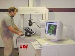
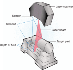
To solve these problems, Herrington became interested in a rapid profile sensor (RPS), or laser scanner, from Laser Design Inc. (LDI; Minneapolis, MN, USA; see Fig. 1). This sensor is an accurate, high-speed, noncontact line-range laser probe that can perform complex-part profile measurements. Line range means that the laser beam is spread out into a plane that forms a line of light on the part under measurement (see Fig. 2). A CCD sensor (two are available) in the probe takes range measurements over the entire line of laser light at the same time instead of measuring just one point as with a point-range sensor, which decreases scan time dramatically.
A 5-mW, 670-nm Lasiris diode laser from StockerYale Canada (Montreal, QC, Canada) is installed in the RPS probe. It is focused down to about 200 µm and uses passive spreader optics to fan the laser light into a plane onto the subject part's surfaces. The sensor mounted in the probe continually triangulates the changing distance and profile of the laser line as it sweeps over the part. The 0.5-in. CCD monochrome sensor, Model 1100 from Cohu (San Diego, CA, USA) with 768 × 494-pixel resolution, is positioned at an angle to the laser plane so that a profile of the part is imaged at 60 Hz on the sensor's two-dimensional photo array, enabling the part to be accurately replicated.
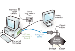
The video signals from the sensor are digitized in an LDI control unit (see photo [above]). This portable unit contains a field-programmable gate array from Xilinx (San Jose, CA, USA), flash converters, and ECL-level differential serial communications to send 8-bit data to the video processor board in the host computer.
The video processor can be operated in any of three modes. In analysis mode, a minimum amount of information is passed to the host to reduce data-transfer time and memory requirements. In frame-grab compressed mode, 8-bit pixel values from only a small window in a scene surrounding the laser line are passed to the Laser Library software. In frame-grab noncompressed mode, 8-bit pixel values for an entire scene are passed to software.
Interfaced to a 16-bit ISA AT computer bus, the video processor changes the image data to parameters that the Laser Library software tools can convert to 3-D coordinates in the probe reference frame. These tools command the video processor to capture, collect, process, and return image information. This software is written in ANSI C and is available in object form for common PC-based development environments. It also supplies a comprehensive set of profile geometry analyzers, including line slope, circle radius, height, angle measurements, step height, and vertex position. Laser Library is compiled in Watcom C++ for running under DOS or Windows 95/98/NT. The probe's RPS-WIN graphical-user-interface software enables users to access, gather, and analyze scanned data by graphical connections to the measurement and analysis functions of the Laser Library software.
Laser scanners can quickly measure large parts without the need for templates or fixtures and generate greater numbers of data points than probes. Since there is no probe on a laser scanner that must physically touch the object, the problems of depressing soft objects, measuring small details, and capturing complex free-form surfaces are eliminated.
"Laser scanning seemed to be just what we needed to improve our reverse-engineering capabilities to match the increase in geometric complexity that we were seeing from our customers' parts," Herrington comments. "But I was a little doubtful about whether an organization of our small size could justify the cost of a laser scanner. It was also necessary to keep the CMM to make higher precise point measurements."
Retrofit not buy
"Then I heard about retrofit kits that offer the ability to attach a laser probe to a CMM," Herrington says. "The cost is only a fraction of what would be involved in purchasing a complete laser scanner because the retrofit eliminates the need to duplicate the machine base and motion-control system, which constitutes the majority of the cost of a laser scanner. I also like the idea of being able to switch back and forth between the laser and CMM probes so as to utilize the best features of both on every project. I selected a retrofit package from Laser Design that made it easy and economical to upgrade our CMM to a laser scanner without losing any of its original capabilities."
Installation involves integrating Laser Design's encoder interface unit with the CMM motion-control-system electronics. The CMM's error-correction table is translated to the format of the computer used to operate the laser probe. Whenever the probe is mounted on the CMM, its orientation relative to the motion transport must be determined. From then on, the laser controller can develop coordinates on the part's surface by combining probe reference frame coordinates with motion transport coordinates.
The probe can be mounted to the CMM in any arbitrary orientation because of an alignment process where the probe-to-CMM orientation is determined. In this process, the probe's relative orientation is saved in the form of a transformation matrix. Then, the collected data are reoriented by the transform matrix; these data can be added to the motion-control-system coordinates to end up with CMM relative measurements. The transformation matrix is determined by measuring a single stationary sphere as it is moved through the probe's measurement field at several different locations. This action forms a grid of sphere centers or points that form a known pattern when the points are multiplied by the proper transformation matrix. An error-minimization technique determines that matrix.
"The laser probe dramatically increases the capability of our CMM, making it possible to provide more accurate evaluations of more-complicated parts in less time," Herrington maintains. "Instead of picking off points one by one with the CMM, we can acquire a million points in a little over a minute without any difficulty with the laser probe. Being able to capture these many points provides the ability to accurately model any surface regardless of its complexity. And we can still reinstall the CMM probe at any time and use it for highly accurate measurements of individual points to verify the laser scan results.
"Software from Raindrop Geomagic (Research Triangle Park, NC, USA) provided with the prober simplifies the process of moving from a point cloud to a CAD model. We can produce a finely detailed CAD model of a complicated physical part in one day. The same job would take about a week on a CMM and would be much less accurate," he adds.
Improved capabilities
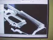
As an example, Herrington pointed to a recent case where a customer provided a shift lever and asked the company to reverse-engineer it to design a testing fixture that would fit perfectly around it. "This part was loaded with contours and had hardly a single flat surface. It would have been virtually impossible to reverse-engineer this part on a CMM. But, with the laser probe, our technician simply 'painted' the part and captured millions of points, defining its geometry to a thousandth of an inch. Geomagic Studio software was then used to analyze the point-cloud data, eliminate redundancy, and turn the data into Initial Graphics Exchange Specification patch surfaces (see Fig. 3). "You can't just load an 8 million-point cloud of data into your CAD system; you need software like Geomagic Studio to work the points into something you can use," Herrington adds.
"Because we could reverse-engineer complicated parts to a high level of accuracy, we began to see an influx of jobs that we would have never gotten in the past," Herrington says. "For example, one customer sent us a die-cast part that was supposed to fit snugly against a glass component but didn't. The geometry was so complex that despite many CMM measurements, no one could agree on which part was out of spec. We created a surface model of our customer's part and then compared it to a model of the actual design geometry using the Geomagic Quality software package that highlights variations between the as-designed and the as-built geometry. The error map clearly showed that our customer's part was accurate."
C. MARTIN SCHUSTER is president and ROBERT THORESON is vice president of Laser Design Inc., Minneapolis, MN, USA; www.laserdesign.com.
Company Info
Cohu www.cohu-cameras.com
Detail Technologiesdetailtechnologies.com
Laser Design www.laserdesign.com
Raindrop Geomagicwww.geomagic.com
StockerYale Canadawww.stockeryale.com
Xilinx www.xilinx.com
