Robot system routes speedometer needles
By Lawrence J. Curran, Contributing Editor
An automotive-parts manufacturer has achieved higher productivity and improved product quality after replacing its manual operations with an automated robot-and-vision system to inspect several types of speedometer and gauge needles. Monroe Inc. (Grand Rapids, MI) has installed a dual-camera-based workstation to assist a pick-and-place robot and motion-control devices in properly orienting speedometer needles for subsequent production processes. These processes include balancing the needles, printing marks on them, and installing end caps for assembly into automobile gauges.
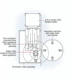
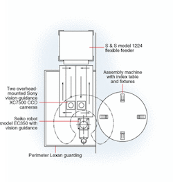
The design task initially appeared to be straightforward, but it did present some challenges for systems-integrator Flexible Automation Inc. (Burton, MI), which implemented a novel motion-control and imaging platform. This platform uses a vibratory parts supply hopper serving two parallel vibrating conveyors, which, in turn, carry the needles under two overcontrol cameras, a robot, and an adjacent rotary-dial table (see Fig. 1).
FIGURE 1. On an integrated robot-and-vision system, the vibratory supply hopper (top) is located above two vibra-tory track feeders (center), which carry the needles into the 4-in.-diameter field of view of two overhead video cameras. After the cameras capture images of the needles, image-processing functions relay the needles' coordinates to the robot's vision software. The robot (bottom center) then picks a needle and places it on the indexing dial table (bottom right). There, the needles are positioned for automatic balancing and for installing end caps.
The needles drop onto the moving conveyors from the supply hopper and are carried under the field of view of two cameras. Each camera looks down on one of the conveyors, acquires images of the needles, determines the coordinates of the needles, and delivers the data to the robot. Upon receiving the coordinate information, the robot picks up the proper needle and places it onto the dial table. The dial table directs the needles to subsequent assembly steps, such as automatically balancing each needle and attaching an end cap.
Ed Osterholzer, president of Flexible Automation, explains that part of the design challenge is that the needles tumble onto the conveyors in random orientation, often overlapping each other (see photo below). This orientation complicates the imaging task for the cameras and the vision software. The vision system must deliver accurate coordinates of the needles as they pass through the approximately 4-in.-diameter field of view of the cameras so that the robot can pick and place a needle precisely on the adjacent dial table for further assembly. The robot rapidly cycles back and forth between the two conveyors in response to commands from a PC-based robot controller, which is driven by vision software.
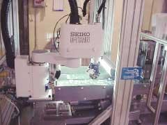
Feeder tracks carry white speedometer needles from right to left for imaging by two cameras (not shown) before being picked by the robot and placed on the indexing table (not visible) for subsequent assembly steps. One of the return tracks can be seen on the far side of the feeder track.
null
Needle work
Needles that are not correctly oriented for the pick-and-place step continue along the feeder conveyors to the end of the belt, where they are dropped down about an inch onto one of two vibrating conveyors that act as return channels. These return conveyors are parallel to, but lie "outboard" of, the feeder conveyors, which are aligned directly with the hopper-type vibratory feeder. The return conveyors move along a slight upward incline, taking the unpicked needles opposite to the feed direction. These needles are then deposited back onto the adjacent feeder conveyor, which passes them under a camera again for possible robot placement.
As needles pass under a camera's field of view, the camera looks for their distinguishing features, such as a pivot post or center hole, for mounting in a speedometer during a subsequent process. Once the vision software recognizes these imaged features, the needles' coordinates are relayed to the PC-based robot controller. As directed, the robot grasps a particular needle, swings it over onto the dial table, and places it in a fixture. The vision system can distinguish needles that are right side up (with post or hole visible) or upside down (with those features not visible). Next, the dial table moves the needles along so that they can be precision-balanced and receive an end cap Last, the needles are palletized, packaged, and shipped to various gauge manufacturers.
While the robot is loading one needle onto the dial table, the camera covering the adjacent feeder track has located the features of another needle. Then, the robot controller calculates the needle's coordinates, and the robot moves to grasp that needle and, in turn, places it into the dial table fixture. This inspection cycle repeats until all the needles on the track feeders have been picked and placed on the dial table. When the vision system detects that there are no more recognizable needles in its field of view, the automated feed system drops a new batch of needles onto the feeder tracks, and the vision-recognition/pick-and-place steps are repeated.
Key elements
In the Monroe needle application, Flexible Automation is responsible for a system that feeds, orients, grasps, and loads the needles onto the dial table, but not for the subsequent assembly steps. To complete the system design, Flexible Automation uses a Seiko D-Tran EC350 vision-guided robot in the initial system installed at Monroe. This robot was built by Epson America Inc. (Carson, CA, USA), a division of the Seiko Group.
The robot-and-vision system also incorporates an Epson RC520 robot controller, an Epson-built Intel Pentium III/850MHz-based industrial PC, Epson Vision Guide 3.0 Windows-based software, and two XC7500 CCD cameras from Sony Electronics (Park Ridge, NJ, USA; see Fig. 2). These 1/2-in., progressive-scan cameras provide a resolution of 659 × 494 pixels, use a C-mount lens, operate at 50 frames/s, and output EIA/VGA signals. High-frequency fluorescent lights are attached to each end of the feeder tracks for illumination.
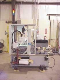
FIGURE 2. Robot-and-vision system uses a vibratory supply hopper (right center) to drop speedometer needles onto feeder tracks. Motion-control devices direct the flow of needles under the CCD video cameras. The PC-based robot controller is located in the lower base cabinet.
null
Flexible Automation integrated the robot-and-vision unit with the vibratory supply hopper, Model 1224 flexible feeder, and 5-in.-wide vibrating-track conveyors built to Flexible's design specifications by S&S Engineering (Canastota, NY, USA). Osterholzer says, "We had to handle the needles without scratching them or marring their finish in any way. We couldn't use a standard vibratory bowl feeder, which might cause scratches." Instead, Flexible Automation glue-lined the flexible feeder and tracks with Brushalon, a 3/16-in.-high padding material similar to Astro-Turf. The vision-guided robot unit uses a 24-V I/O scheme to communicate with the dial table and programmable logic controller.
Since the initial system installation, Flexible Automation has installed two identical vision-guided robotic systems, but with Epson SCARA (Selectively Compliant Articulated Robot Arm) robots. A fourth system implements machine vision to automate the placement of end caps on the speedometer needles and to palletize the finished products.
Company Info
Epson America Inc. www.robots.epson.com
Flexible Automation Inc. www.flexautoinc.com
Monroe Inc. www.monroeproducts.com
Sony Electronics Inc. www.sony.com/videocameras
S&S Engineering www.ssengineering.net


