Machine vision checks shock-absorber-seal integrity
Ensuring the smooth movement and leakage resistance of shock-absorber seals requires accurate, rapid geometric measurements.
By Andrew Wilson, Editor
With more than 80,000 products in its portfolio, Freudenberg Anlagen- und Werkzeugtechnik is one of the world’s largest manufacturers of sealing products for the automotive and aerospace industries. “Because of the large variety of products produced by the company, quality assurance was, in the past, limited to random sampling,” says Thomas Bauernhansl, general manager. “Now, however,” he says, “automatic optical inspection systems integrated into the production process are used to identify manufacturing processes that may cause product defects. Using feedback-control mechanisms, these systems can help reduce the number of product defects and increase the quality of production processes to a six-sigma level.”
One of the highest-volume products produced by Freudenberg is shock-absorber seals. According to Bauernhansl, the company supplies these products to every automotive manufacturer worldwide. “In the design of shock absorbers, damping effects are highly dependent on the smooth movement, dust resistance, and leakage resistance of the seal. Should any part of the seal not meet specific dimensional tolerances, it will not function properly and must be rejected.”
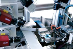
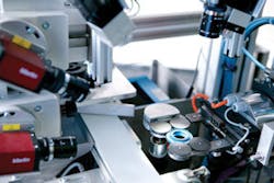
To ensure this does not occur, measurements of the seal lip and center diameter must be accurately made, as well as checking for flashing, bubbles, or missing material on the elastomeric material. And since the seals often use metal-reinforcement rings in their design, the presence or absence of the rings must also be detected. To do this, Freudenberg has developed an automated system based on custom specifications and off-the-shelf machine-vision peripherals (see Fig. 1 on p. 46).
Innovative approaches
After manufacturing, each part is placed on a conveyor belt where it is moved single file into the imaging workstation. As the seal passes a photoelectric sensor, the part triggers a PLC that, in turn, actuates an x-y pneumatic gripper that picks that part from the conveyor. The part is placed onto a rotary mechanism where it is inspected by the vision system. Using three FireWire cameras, the part is imaged from the top and the side and at 45°. While the camera placed vertically measures and inspects the seal lip and outside diameter of the part, the camera placed horizontally measures and inspects the outside diameter of the seal. To image the inside of the seal, the camera placed at 45° captures images of exactly one-half of the inside seal.
To properly illuminate each part, individual white LED spotlights from SAC illuminate the part from all three angles. Because these lights provide a well-defined diffuse beam of light, they maximize the contrast of the seal at all three angles and can be adjusted so that any specular reflections from the parts are minimized. “Increasing the contrast of the part in this way allows more effective measurements and image analysis to be made,” says Wolfgang Embach, project engineer at Freudenberg.
System design
In design of the system, three Marlin FireWire cameras from Allied Vision Technologies are interfaced to a Vision PC linked with an S7 PLC from Siemens. With 1024 × 768-pixel resolution, these cameras are strategically placed to obtain the highest-quality images. “For example,” says Embach, “by placing the vertical camera over a top section of the seal with a 30 × 30-mm field of view and capturing images every 70 ms as the part is rotated at 108 revs/min, several high-resolution images of the top surface of the part can be captured. In this way, the camera can capture eight images at every 45° as the part rotates, providing additional image data for analysis. These images are used to measure the parameters and quality of the outer diameter and seal lip.
Similarly, the cameras positioned at 45° horizontally are also operated in this manner. While the angled camera looks for surface defects and flow marks in the inner area of the seal, the horizontally positioned camera checks the outer diameter of the seal. “In both cases,” says Wolfgang Embach, a project engineer with Freudenberg, “the system must characterize the images for missing material and flashing or small metal objects that may have occurred in manufacturing.”
Since only one side and one-half of the inside seal can be imaged in this way, the part must be rotated and replaced on the rotary mechanism. Once measurements are made on the first side of the seal, the machine-vision system triggers the rotary mechanism to stop, and the pneumatic handling turns it and replaces it on the rotary mechanism. The image-processing process is then repeated. “In effect,” says Embach, “the system then has a complete image of the top, bottom, and the inside of the seal.”
After each part is imaged and checked for possible defects, the machine-vision system triggers the pneumatic gripper to place the inspected parts onto a second conveyor. On this conveyor, the inspected parts are separated into “good,” “bad,” “suspect,” and “rework” parts into different boxes, according to the inspection results.
Characterizing parts
To characterize each of the parts as they are inspected, Freudenberg chose to use the Coake graphical programming language from SAC. “Using this programming language,” says Embach, “developers can create specific programs using drag-and-drop graphical icons from a program editor, eliminating the need for C programming. As well, the software also allows images to be captured and saved and logged with any possible production errors that may have occurred.”
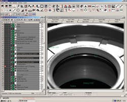
Measuring the maximum width of the lip seal centered within the part is one of the many functions performed by this software (see Fig. 2). Eight images from the angled camera are digitized into the memory of the PC. As each image is captured, regions of interest (ROIs) within the seal are highlighted using the ROI tool from Coake, and the inside and outside diameters are measured. This process is then repeated for all eight images and the statistical data stored in memory. If this measurement does not fit the statistical measurement requirements set by the part, then the part is rejected.
“To detect for flashing on the bottom dust lip, a different approach is used,” says Embach. “After the image is thresholded, a best-fit circle highlights the lip of the part. Should any extraneous material be present, the system will not return a best fit and the part will be rejected. Once again, this measurement is made on all eight images from the camera, and, if specific parameters are not met, the part rejected.”
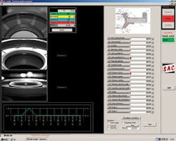
“Of course,” says Embach, “it is also important for the user of the system to visualize the results of the numerous measurements that are being made. To develop this interface, SAC’s Coake GUI was used to both display the results from all three camera angles and the results of the measurements in real time” (see Fig. 3). Such a display not only shows images from the cameras in real time as the part is being inspected, but charts statistics of the parts as they are measured. These include the interior and external diameter of the part and whether the metal-reinforcement ring is present.
“As well,” continues Embach, “the interface can display a statistical graph of good, bad, reject, and suspect parts as they are being produced. Thus, for example, if 10 bad parts are produced with the same fault, the manufacturing production process can be stopped and the fault corrected before hundreds of thousands of parts are produced.” At present, this procedure is performed manually, but in the future Embach expects this to become a fully automated process.
null
features, advantages, benefits
“To inspect our shock-absorber seals at high speed requires an innovative approach both in the design of automated handling systems and machine vision,” says Wolfgang Embach, a project engineer with Freudenberg Anlagen-und Werkzeugtechnik. “For example, the system needs to inspect the sides and inner surface of the elastomeric seal.
“To do this, the machine-vision system must image both sides of the seal and its inner surface and check for the presence or absence of the metal-reinforcement ring. This required the development of an automatic handling system that can both rotate the part to allow 360° images to be captured and turn the part so that each side can be imaged effectively.”
