Vision system shortens fiber-alignment time
By C. G. Masi,Contributing Editor
Reducing cycle times speeds up production and makes a company more efficient; therefore, the company saves money. A telecommunication-components manufacturer recently asked the Technology Integration Division of SES Technology Integration (Boulder, CO), integrator of hardware and software systems for industries ranging from automotive and aerospace to telecom, for help reducing the cycle time on its pigtailing machine that attaches single-mode optical fibers to laser diodes.
Says Kerry Quinn, an SES company executive, "The problem in this case had to do with the very precise tolerances required to align an optical fiber to a solid-state laser diode." The tolerances on the position and direction of the laser beam exiting its metal TO package are loose enough that a lengthy search had to be done to find the correct final alignment for each assembly. Even a machine-vision-mediated coarse alignment of the package and fiber left a search taking up to two minutes.
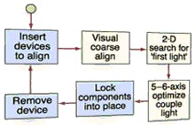
The original coarse-alignment system used two images—one looking vertically down and the other looking horizontally—to determine where the package was with respect to the fiber (see Fig. 1). A motion-control system moved the fiber to where it expected the beam to be, assuming the laser beam exited the package where it was supposed to and that the optical-fiber core was centered with respect to the fiber's cladding.
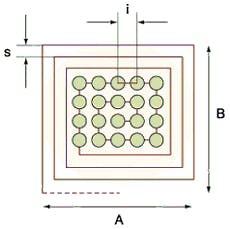
Next, the motion system had to perform a spiral search to center the beam on the core (see Fig. 2). Because the coupling efficiency into a single-mode fiber depends on the angle at which the light enters the core, the motion system had to perform a similar search to find the right angle.
Most of the time required to attach the fiber to the laser goes into making those two spiral alignment searches. How long those searches take depends on how good the coarse alignment is. The wider the initial misalignment, the more time will be spent making the spiral searches.
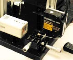
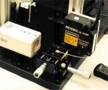
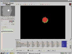
Making improvementsSES engineers attempted to make the spiral-search routine more efficient. "The best that we could do was a 37-s average alignment time," Quinn reports. That just wasn't good enough. They were convinced they could do better by improving the coarse-alignment system. They reasoned that, since the biggest tolerances were for the position and angle at which the beam leaves the laser, they could get improvement by aligning the fiber to the beam itself, instead of the package. So, they developed a system that, using one CCD camera, locates the beam's optical axis in space. The system uses an alignment machine that locates the laser beam in space (see photo on p. frontis). That information then goes to the pigtailing machine to improve the starting point for its search algorithm (see table).The engineers used National Instruments (NI; Austin, TX) IMAQ vision hardware and software to capture images from the camera—Taiwan Regular Electronics Corp. (Taiwan) model TC-2270, a CCD array with 537 x 505-pixel resolution and a 0.25-in. (6-mm) form factor manufactured by Sony Electronics (San Jose, CA). NI motion-control products were used to run the mechanical stages that manipulate the camera and other movable system components (see Fig. 3). The overall application was written using NI LabVIEW graphical programming software.
The camera, looking down the TO package's cylindrical symmetry axis, determines the x1 (horizontal) and y1 (vertical) coordinates of the beam as it crosses the z = L1 plane. The camera moves back until its CCD array is at the z = L2 plane, then finds the new coordinates (x2 and y2) where the beam intercepts that plane. Since two points determine a line, that is enough information to determine the beam's optical axis.
This measurement is done in one device, with the fiber presentation, fine alignment, and bonding done in another machine. This means that the beam's optical axis has to be relocated in the second machine. The engineers rejected the idea of registering the package outline with respect to the two machines' coordinates as impractical at the tolerance level required. Instead, they added an easily found coordinate system to the package that would move with it.
They add this "package coordinate system" by machining a small indentation into the package shaped like one internal corner of a cube. The three axes lie along the three dihedrals where the cube sides meet. To locate these axes relative to the machine's coordinate system, they use an off-the-shelf, laser-based noncontact linear variable displacement transformer (LVDT; Keyence of America; Woodcliff Lake, NJ) to probe the surfaces. The LVDT has a resolution of 10 nm and a 20 x 12-µm spot size.
The LVDT is mounted via a micromanipulator stage to the machine, so it is automatically referenced to the machine coordinate system. In operation, it acts as a coordinate-measuring machine (CMM) to locate—in three dimensions—points on the inner surfaces of the notch. The system actually measures seven points on each surface to improve accuracy and average out surface imperfections. Once the three planes are located in the machine frame of reference, it is a simple mathematical operation to find the loci where the planes intersect. The intersection of the x-y and y-z planes determines the y axis, and so forth.
The measurement machine measures both the optical axis and the package coordinate system relative to its own coordinates and transforms the optical-axis location into the package coordinate system. This information goes along with the package to the pigtailing machine.
The pigtailing machine has a similar CMM, which again measures the three faces of the notch to find the package reference frame relative to its (pigtailing machine) coordinate system. Then, it uses that information to transform the optical-axis-location information from the package frame to its machine frame. With that information, it can accurately place the optical fiber along the laser beam's optical axis for a coarse alignment, providing a factor-of-ten improvement in spiral-search time.
With this system, the major mechanism for initial misalignment is nonrepeatability of the fiber position in the grippers that present it to the laser beam. The step of placing the fiber into the grippers is done manually.
Company InformationKeyence Corp. of AmericaWoodcliff Lake, NJ 07675Web: world.keyence.comNational Instruments
Austin, TX 78759
Web: www.ni.com
SES Technology Integration
Denver, CO
Web: www.sestechnologyintegration.com
Sony Electronics Inc.
San Jose, CA
Web: www.sel.sony.com
Taiwan Regular Electronics
Tao Yuan Hsien, Taiwan
Web: www.trcctv.com
