Military base orders IR imaging system to detect intruders
Military base orders IR imaging system to detect intruders
By John Haystead, Contributing Editor
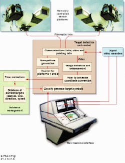
The Ministry of Defense (MoD) in England is using infrared (IR) imaging technology to protect its military facilities from intruders. It has selected a personal-computer (PC) based automatic detection and infrared surveillance (ADIRS) perimeter-security system to monitor a 4 ¥ 1-km area of land or water for automatically detecting and tracking unfriendly intruders (see Fig. 1).
Built by Octec Ltd. (Bracknell, England), the ADIRS system links as many as three remote-monitoring platforms to
a central PC-based image-processing and control console. Positioned at high vantage points in the surveillance area, each platform is equipped with both a TV camera and an infrared thermal-imaging camera mounted on a remotely controlled pan-and-tilt head. The two cameras survey the entire security zone approximately once every minute.
During surveillance, imaging data from the IR camera and sensors are initially processed for initial target detection and identification. Upon a detection of a target, the console operator manually locks the TV camera onto the target. Next, the ADIRS system automatically classifies and displays the target, generating an alarm for the operator when preprogrammed target parameters are met.
The ADIRS system is particularly useful for monitoring shore-based installations where the construction of physical barriers would be impractical due to changing water levels and boat traffic. At a typical Baywatch MoD installation, one of two ADIRS remote platforms surveys a site by covering a surveillance area of 0.9 km out from the from shore and 2 km to either side. The second remote platform looks out to sea for a distance of 1 km and 3.8 km laterally. Both platforms seek to protect the installation`s marine security corridor.
According to M. Smalley Ceng, security facilities executive, MoD Special Services Group, surveillance systems based on video motion detectors (VMD) were also considered for the Baywatch installation, but "these proved to have an unacceptably high false-alarm rate." On the other hand, Ceng says, "thermal-imaging sensors provide strong target-to-water contrast at night, require no artificial illumination, and provide greater detection range."
On patrol
Infrared cameras provide the targeting and identification data for the ADIRS system. Although a variety of IR cameras can be used, a dual-field-of-view, 8- to 12-mm-band system is usually specified. According to Nigel Bonsor, Octec director of new business development, IR imagers operating in the 3- to 5-mm band are more sensitive overall, but they are also more susceptible to background clutter from solar reflection. In addition, the peak thermal-emission-sensitivity range of 8- to 12-mm systems corresponds better to objects at ambient temperatures (such as humans), whereas 3- to 5-mm systems are aligned more toward much warmer objects. "Because the ADIRS system is primarily looking for objects at ambient temperature, it`s more suitable to the application," says Bonsor.
The Baywatch installation also implements Agema 1000 imagers from FLIR Systems (Portland, OR). The imagers` field of view (FOV) is switchable from 3 to 12 with the narrower beam used in normal detection mode. The camera`s scan sweep speed is typically set to one FOV per second, generating 25 frames of data for each FOV while still allowing the system to scan the entire surveillance area once a minute.
Although faster sweep speeds (such as 5 FOV/s) could also be set, these speeds would generate fewer target images at the same frame rate. As explained by Bonsor, "the more frames of data we can obtain per field of view, the better the system`s ability to reject false targets." A small target would appear in all 25 frames of a single FOV scan, during which time it would move from right of frame to center. The ADIRS system is programmed to make target determinations within ten frames of data.
Image processing
The analog output from both the IR and TV cameras are transmitted from the remote platforms over fiberoptic links, supplied by Fiber Options Inc. (Bohemia, NY), to the ADIRS control console located approximately 3 km away. To survey difficult terrain, microwave or other links can also be used. Bidirectional command-and-control RS-232 serial data at 19.2 kbaud are transmitted in parallel with the video stream; an additional bidirectional audio-signal path is provided for use in maintenance work.
The ADIRS target-detection and control subsystem comprises several processor boards plugged into a standard 19-in.-rack PC with a dumb backplane. It first converts input optical transmission signals to copper-wire electronic transmission signals. These electronic signals are then distributed to the various functional elements of the control system by an Octec VCB2000 VME 8 ¥ 8 video-routing switcher. Because the television video signals receive no further image processing, they are routed directly to one of the system`s two Marathon digital video recorders from Radamec Electronic Systems (Chertsey, England) and to the console`s TV monitor.
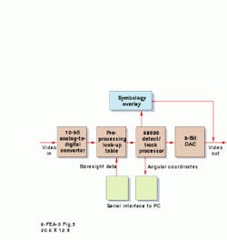
The infrared signals are fed into two Octec Adept 30 video-tracker image-processing cards, one for each sensor (see Fig. 2). An on-board 10-MHz analog-to-digital converter first digitizes the IR signals to 512 ¥ 512 digital images at 8-bit resolution. It then passes the pixel data through a look-up-table preprocessor, which performs local thresholding of the image for enhancement and clutter rejection. "We could digitize at a higher rate," says Bonsor, "but we find that this resolution and speed are suitable for most image-processing applications."
The Motorola 68030 detect/track processor in the Adept 30 video-tracker image-processing cards is programmed to detect anomalous clusters of pixels, or "hot spots," in the images. A hot spot is either warmer or colder than the pixels surrounding it in the image. A number of Visual-C-based, target-detection modes can be programmed, but the algorithms will generally discard targets considered too small (less than 20 pixels, for example) or containing distorted aspect ratios (that is, one to two pixels deep extending the length of the horizon). The total detection area can also be divided into up to 16 different subzones with different alarm criteria programmed for each subzone.
Simultaneous with the receipt of image data, the video-tracker image-processing cards are also continuously receiving pointing-angle data from the pan-and-tilt heads on the remote platforms. The elevation and bearing angles of the camera heads are controlled and monitored by a rack-mounted 133-MHz Pentium PC processor via an 8-channel, RS-232 serial communication card, which also provides the links to the video-tracker image-processing cards.
The 68030 detect/track processor automatically correlates the pointing angle and pixel-image data to calculate the relative angular azimuth and elevation position of the target. Because the camera platform is moving, however, and because the IR sensor is a scanning, as opposed to a staring, array, every line of the raster scan is offset slightly as the picture is constructed. The processor therefore calculates and interpolates the platform position for each individual line of data.
If a hot spot meets the proper parameters, the video-tracker image-processing cards will generate an alarm and pass the combined pixel/angle data set back to the PC processor for conversion from polar to cartesian (x, y) coordinates. Because the PC is preprogrammed with precise camera-position information (such as height above ground level), it can in turn calculate the geographic position and size of the target object in the image and then plot it on a grid-coordinate system for display at the control console.
If a target is moving, comparison of repeated position calculations can also provide a rough estimate of its speed. Moreover, by continually recording the target`s speed and position from scan to scan, track-extraction algorithms can then predict its future location should the target temporarily disappear from view. Data for more than 100 targets can be maintained simultaneously in the PC`s 32-Mbyte RAM memory.
When alarm mode is activated, the PC control system automatically assigns one pan-and-tilt head to continuously track the target. To do this, the PC sends the azimuth and elevation coordinates of the target back to the remote platform, which can shift its boresight to the designated target position within three seconds. The ADIRS system will then continue to update these commands as new target coordinates are calculated.
Control console
The operator`s control console houses three color monitors. The center 19-in., 1280 ¥ 1024-pixel display from Conrac (Weikersheim, Germany) is used for primary control and display functions and for overlaying the particular area of interest onto a color map of the installation. Each target is classified and marked with a specific symbol. Using a touch-sensitive screen interface, the operator can call up individual target data such as its type, course, and speed.
Targets that do not meet predetermined identification criteria are automatically identified as potential intruders and immediately brought to the attention of the operator. A list of possible target types is then displayed on screen for operator selection. Targets are initially shown in red, and then are changed to yellow, green, or blue as they are designated as hostile, harmless, or friendly, respectively. A track tail is also displayed that gives an indication of target speed and direction. Unless the operator requests additional time for evaluation (in 30-s increments), the system will automatically switch back to scan mode.
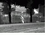
Located above the center monitor are two 14-in. TV monitors from Panasonic (Secaucus, NJ). In normal scan mode, both monitors are used to display live infrared images, one for each remote platform. When the system is in alarm or manual mode, however, one display is used for IR imagery while the other displays TV imagery to help the operator with target identification. The color TV camera is boresighted to the IR sensor and has a 12:1 zoom capability (see Fig. 3). Additional monitors can also be connected to the system for viewing by other security personnel.
In alarm mode, both IR and TV images are automatically recorded onto two digital video recorders for rapid replay. As noted by Bonsor, "Although each recorder can simultaneously record up to four different video inputs in multiplexed form, there is only one replay stream possible at a time, and we wanted to be able to play back both IR and TV imagery simultaneously." Data are recorded on each recorder`s 2-Gbyte hard drive, which can store up to two hours of compressed video data.
FIGURE 1. Using infrared and television cameras, an automatic detection and infrared surveillance military-security system finds and identifies moving targets (persons) passing through a defined observation area. Two remotely controlled sensor platforms deliver both infrared and video images over fiberoptic links for processing by a target detection and control subsystem, a man-machine interface, and a database-management subsystem.
FIGURE 2. Based on VME bus architecture, the Adept 30 video-tracker image-processing cards from Octec Ltd. Receive video data from the sensor platforms. On-board processors detect and identify targets based on digital thermal-image data. Linked to the PC-based control system via an RS-232 serial link, the cards also perform image processing for hot-spot detection, field-of-view compensation, symbology representation, and target angular coordinates.
FIGURE 3. Infrared sensors operating in the 8 to 12-mm range prove optimum for detecting objects with close to ambient temperature, such as human intruders. In scanning mode, the Agema 1000 infrared camera first scans a wide area (top) and then zooms in on its target for detailed inspection (bottom).


