Seco Tools Installs Custom Solution to Inspect Indexable Inserts Used in Machining Operations
Editor's note: This article was updated September 30, 2024, with new information.
Seco Tools (Fagersta, Sweden) installed an automated system—using AI, machine vision, and robotics—to handle and inspect indexable inserts, also known as changeable cutting edges.
“Our solution is designed for those who work closest to the machines, those who previously performed manual tasks like visual inspections, which we are now replacing with automation,” explains Martin Tobias Lithner, lead data scientist at Seco.
The company hired Xactools (Bönnigheim, Germany) to help develop the system. The automation and machine vision integrator, which develops measuring and testing solutions, designed and installed the custom solution in 2022.
Indexable inserts, which come in many shapes, are manufactured using a sintering process in which powdered metals and other materials are pressed into a shape and then sintered, or bonded together, using heat and pressure.
After the sintering process, the cutting edges of the inserts are refined by rounding them and then grinding, blasting, and coating them.
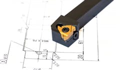
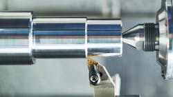
Indexable inserts are used in machining operations to remove material from a workpiece by cutting, drilling, or shaping. The inserts are made of hard materials such as metal or carbide, so they can withstand the machining process.
The indexable inserts are screwed into a tool holder, and many of them have a fixing hole in the center to ensure a tight hold. When the cutting edge becomes dull, the insert can be flipped to expose a new edge, or it can be replaced with a fresh insert.
To inspect the indexable inserts, the team developed an automated process that occurs right after sintering. "The earlier defects are detected in the process, the better and cheaper it is to rectify them," says Marvin Krebs, managing director at Xactools.
Before the adoption of the automated solution, Seco Tools relied on a manual spot-checking process of a statistical sample of parts per production order.
In general, inspection at the company takes place three times during the production process: after sintering, after grinding, and at the end before they are packaged into pallets bound for a customer.
Components of the Robotic Solution
The robotic solution is a multi-station system housed inside a glass enclosure that is 3 x 3 m in size.
Inside the enclosure, there is a rotary table with three nests, or workstations, and two Spider RS4 550 mm Series four-axis, SCARA-type robots from Epson (Suwa, Japan). The solution also includes a total of eight cameras (both line scan and area scan models) with resolutions between 5 and 30 MPixels from several manufacturers. All lens for the area scan cameras have a fixed focal length.
Other machine vision components include a 1 x 1 m LED lighting screen from Planistar Lighting Technology GmbH (Himmelstadt, Germany) and a multi-GPU computing stack and industrial monitor that sit directly outside the system.
While some traditional machine vision algorithms are used in the solution, most of the image analysis is enabled with convolutional neural networks, which the team developed using DENKnet, AI-based image evaluation software from IDS Imaging Development Systems GmbH (Obersulm, Germany).
How the AI-Enabled Vision System Works
The indexable inserts are arranged on crucibles, or round trays, when they enter the sintering oven. The trays, which can withstand the heat and pressure of the sintering oven, are about 400 mm in diameter and about 3.5 kg in weight when they are empty.
After the crucibles come out of the sintering oven, employees load them onto a lift and a motorized mechanical handling system stacks the crucibles inside the machine vision system. The mechanical system then takes a crucible out of the stack and brings it to the robot unloading area.
Here, an area scan camera takes an image of the entire tray, providing data so that an object detection algorithm can locate each indexable insert on the tray. Another algorithm analyzes the image data to provide grabbing points for the robot.
Next, the first Epson robot picks up each insert separately and holds it over a second camera—also an area scan camera. Based on this image, algorithms determine the contour of the indexable insert and if there are defects on the bottom of the insert.
In the next step, the robot places the insert on a magnetic nest located at the first station at the rotary table. The nest is a flat surface with a magnet underneath that holds the indexable inserts in place.
Once the robot deposits the insert on the magnetic nest, it moves out of the way, and a third area scan camera moves into position above the station and snaps an image of the insert. From this information, algorithms analyze the top of the insert for defects, its position from X and Y coordinates, and rotation information.
At this point, the round table rotates clockwise, moving the insert to the second station.
Once positioned at the second station, two line-scan cameras, one positioned on the top and a second on the side, scan the cutting edge of the insert as it is rotated. Each camera also moves as needed to make sure that the cutting edge of the indexable insert is always within the focal plane of the camera.
Algorithms recognize and classify each indexable insert as OK or NOK. Even tiny defects and irregularities, such as cracks or scratches, are classified as NOK.
The robot puts parts that do not pass inspection into a drawer so that human workers can retrieve them.
However, parts that are OK need to be placed on a pin pallet or a nest pallet, so they can exit the inspection system and continue to the next step in the manufacturing process.
The table rotates and the indexable insert moves to the third station.
At this station, there are two positions, so two pallets can be positioned side-by-side with an area scan camera positioned above each pallet.
To facilitate palletizing, the robot, with an indexable insert in its gripper, moves over a camera located above a pallet—either a pin or nest variety. The camera snaps an image, which provides visual information about the contour of the insert and the position of the hole in the center of it. The robot then holds the insert over a camera located below it to get final positioning information.
This helps the image-analysis algorithms determine where on the pallet the insert should go, so the second robot can place it precisely on pin or recessed space on the pallet.
Using these images, algorithms also detect all pins or recessed spaces in a pallet to determine if any of them are damaged. If they are, they will be skipped in the palletization process.
Once a pallet is full, it is ready to exit the inspection system.
The total cycle time per indexable insert is four seconds and the system detects defects as small as one thousandth of a millimeter.
Geometry Families Complicate Machine Vision Image Analysis
Indexable inserts come in 16 basic shapes and countless varieties within each shape category due to deviations in size, thickness, cutting edge, surface finish (matte, shiny, reflective), color, and material composition (carbide, metal).
The Scandinavian manufacturer has nearly one hundred geometry families, or subcategories, within those basic shapes, or about 2,800 different types of indexable inserts.
As a result of the large variety of inserts to inspect, designing the system was challenging in several ways.
Changing Robot Grippers on the Fly
First, robots need different grippers, depending on the geometry of the indexable insert and the type of crucible. For example, some crucibles have long slots embedded in them to hold rectangular inserts while others have pins to hold round inserts.
To solve this problem, Xactools built two gripper stations (one for each type of gripper) and created an automated process, allowing robots to change grippers as necessary.
The team programmed a “look up” table into the software to describe what gripper to use for each geometry.
The software also communicates with the manufacturer’s enterprise resource system from SAP (Walldorf, Germany) to find out what type of insert will be in the next load to go into the inspection system.
Deep Learning Algorithms Overcome Inspection Challenges
Using the DENKnet, the team built a series of algorithms to complete the handling and inspecting processes.
Although there are more than 100 geometry families, the training went smoothly, Krebs says. The team used about 15-20 images for each of seven basic geometries and then additional images showing different variations within each geometry family as well as different defects of the top, bottom, and cutting edge of the inserts.
Lithner explains the training process, “Currently, we are focused on training the network to handle over 900 unique geometries, which is a very vast and complex task in itself. As the network matures and consistently identifies deviations within these insert geometries, the process will become more streamlined—akin to pressing a start button on a machine.”
At that point, Lithner says, “If a new product somehow introduces unexpected variations in these defined deviations, the approach is a bit straightforward: we will annotate these deviations, adding them to the training dataset. This expands both the data and the model’s understanding.”
Accurate Pick and Place and Inspection
The system achieves high accuracy rates, such as:
- Picking inserts from crucibles after sintering with 99% accuracy
- Placing inserts on to pin or nest pallets with 99% accuracy
- Catching more than 99% of defects.
Krebs sums up the project, saying that "using AI for these kind of parts is the only thing to do—or is the only way to solve it." Otherwise, he says, there would be "a lot of hard coding to adapt to all these different kinds of geometries and also grayscale values and these kind of things. Of course, the same is also true for the variations."
About the Author
Linda Wilson
Editor in Chief
Linda Wilson joined the team at Vision Systems Design in 2022. She has more than 25 years of experience in B2B publishing and has written for numerous publications, including Modern Healthcare, InformationWeek, Computerworld, Health Data Management, and many others. Before joining VSD, she was the senior editor at Medical Laboratory Observer, a sister publication to VSD.


