Machine vision system identifies and locates pickable parts for robotic assembly cell
Machine vision system locates busbars on a backlit conveyor and verifies proper robotic assembly of electrical receptacles
Pop-up power and data outlets must fit into various styles of desks, workstations, and other modular furniture. After all, outlet size, shape, color, and circuits must meet various design and electrical requirements for use in numerous hospitality, healthcare, teaching, and office environments. As a result, manufacturers of these devices may produce several dozen different outlet models.
To produce such outlets, technically dubbed duplex receptacles, manufacturers often employ manual operators for assembly, inspection, testing, and packaging before they are shipped out to furnishing suppliers or for final installation at customer sites. That’s essentially how Byrne Electrical Specialists (Rockford, MI, USA; www.byrne.com) formerly produced its electrical receptacles. According to Byrne Automation Engineer Dan Wierenga, the company previously relied on two dedicated manual assembly lines.
“With those two lines, it was a real challenge to keep up with peak demand,” he explains. That’s one reason why the company turned to machine-builder Criterion Manufacturing Solutions (Comstock Park, MI, USA; www.criterionms.com) to develop an automated receptacle production machine. The machine consists of three identical assembly cells with a shared output conveyor that feeds a test-and-pack cell where final 3D inspection, testing, and pack out for shipping are all automatically performed (Figure 1). In the new system, operators set current job number and order parameters such as color, size, and outlet count per case using the HMI, then manually load front shells and back plates, as well as positive, neutral, and ground busbars into hoppers on the machine. Busbars are separated by a vision-guided robot as they travel down the conveyors.
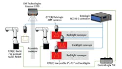
To do so, each assembly cell combines three custom-built, three-tier, part-sorting conveyor systems, two MZ07, six-axis robots from Nachi Robotic Systems Inc. (Novi, MI, USA; www.nachirobotics.com), and a four-camera machine vision system from Datalogic (Bologna, Italy; www.datalogic.com). Another robot inserts the separated busbars into the outlets, which are then sent by conveyor to the final pack out cell, where a Gocator 3210 3D snapshot sensor from LMI Technologies (Burnaby, BC, Canada; www.lmi3d.com) performs final inspection, and another Nachi MZ07 robot packs the finished products for shipping.
Criterion Manufacturing worked very closely with engineers at Byrne and teamed with automation distributor Industrial Control (Zeeland, MI, USA; www.industrialcontrol.com) developing specifications for the machine vision system at the center of this automation project.
“Quickly sorting through a pile of busbars from bulk storage into an orderly stream of parts that can be readily handled by a robot and assembled by automated equipment requires a dynamic vision system with fast and robust object recognition,” says Industrial Control Senior Account Manager and Manufacturing Engineer Jake Hall.
Each part sorting conveyor system has a dedicated camera acquiring images of busbars as they pass over a section of the conveyor with a built-in back light to highlight the profile of each part, identifying parts and sending coordinates to the attending robot for picking. The other robot assembles the outlets, which are imaged by the fourth camera for assembly verification and inspection prior to being moved to the pack out cell.
“We teamed with Industrial Controls because of their machine vision experience,” says Wierenga. “They offered a lot of support, advice, and education on these systems.”
Cascading conveyors
The electrical receptacle components themselves were originally designed many years ago to be built by hand.
“It was never considered that a robot would ever be building these parts,” says Wierenga. “So, we had to optimize the parts, and the interfaces between the parts, for automated robotic assembly.”
Each outlet has five parts: a two-part plastic housing made up of a backer and faceplate and copper busbars for ground, neutral, and line. Each busbar has a unique design and they tend to tangle together.
“We have 9 different heights, 25 different colors, 15 different circuits, and dozens of different busbar designs. When you do the math, there are several hundred different outlet variations produced,” says Wierenga. “Sorting and assembling such a large number of these different types of parts using the same automation system proved quite challenging.”
To address this, a multi-tier, sorting and singulation system was developed based on cascading conveyors from QC Conveyors (Batavia, OH, USA; www.qcconveyors.com). The first and slowest-moving conveyor takes a bundle of busbars dumped randomly from an elevated hopper and drops them onto a lower, faster-moving middle conveyor.
The action of parts falling slowly from the top conveyor onto the faster moving conveyor below is intended to untangle and break up busbar bundles to create separation, which is important to enable the robot to pick each part cleanly without disturbing or entangling with others around it.
The busbars travel along this conveyor on a 10-inch wide translucent belt. Near the end of the conveyor section, a Datalogic E151 2 MPixel, monochrome, GigE camera mounted 4.5 feet overhead continuously acquires images of the parts moving along the conveyor. Image data is transferred via the GigE Vision cable to a Datalogic MX-80-E controller.
“Since the copper busbars are metallic and have irregular shapes, they tend to reflect ambient factory light,” says Wierenga. Because such reflections can complicate image formation, processing, and analysis, Criterion Manufacturing integrates custom-built, red LED backlights measuring roughly 10 x 14 inches into each of the three part-sorting conveyors. The light fits under the belt and between the conveyor’s aluminum extrusion framework.
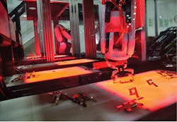
By projecting even illumination from underneath the busbars toward the camera, the backlight highlights a silhouette, negating the surface detail and minimizing the impact of reflections off the busbars, and the bright background generates intense contrast at the edges of the parts (Figure 2). According to Wierenga, machine shrouding and infrared filters on the camera optics also minimize reflections from ambient lighting that can cause unwanted reflections in the images.Pickable parts
To identify and locate pickable parts for the robot, developers configured the Datalogic IMPACT software running on the controller to analyze acquired images using blob and part matching tools, according to Hall. These tools enable the system to quickly identify busbars suitable for picking. Such parts must be the right size, shape, and orientation, and be clear of parts within 5 mm around them.
If busbars passing over the conveyor backlight are in the wrong orientation or entangled together, they continue to the end of the conveyor and fall onto a third conveyor moving in the opposite direction. This conveyor returns them to the hopper, which elevates and dumps the parts back onto the top conveyor for continual recirculation.
When the vision system identifies a pickable part, it signals the PLC to stop the conveyor, acquires another image, verifies it’s the correct part, calculates its position and orientation, and sends the coordinates to the robot for picking. The robot picks the part off the backlight conveyor and sets it in one of two staging nests (Figure 3). The robot simultaneously tends two other identical part sorting conveyor systems that operate in the same way, each feeding a different type of busbar. While the first three cameras work with the robot tending the three busbar sorting conveyors, the fourth camera works with the second robot, which is responsible for building the outlet assembly.Before an outlet build starts, the fourth camera first acquires an image of the empty assembly nest. The vision system analyzes this image to make sure that the nest is clear of any foreign debris. Once the active nest is checked for errant material and confirmed clear, the assembly robot picks a faceplate from a hopper, placing it in the active nest, which captures the part in a fixed position for assembly. Next, the robot picks the appropriate busbar from the staging nest and places it into the faceplate.
Meanwhile, the busbar-picking robot continually works with the vision system to pick the required busbars for each build from the part sorting conveyors and refill the staging nest for the assembly robot. After the three busbars are placed, the assembly robot takes a backer from another hopper, and places it on the faceplate.
Finally, the fourth camera acquires another image of the assembly, which the vision system analyzes to ensure that the backer is properly seated and is fully engaged with the faceplate. If not, the nest purges and another build starts without any intervention. If the part passes, the robot removes it from the active nest and places it on another conveyor, linking all three assembly cells to the pack-out cell.
Mixed-model processing
Each of the three identical assembly cells can build a different outlet model, simultaneously, achieving the ability for mixed-model processing, where each model type is packed out in its own box at the end and ready to ship. The conveyor linking the three cells collects and moves all of the completed outlets to a three-axis, cartesian gripper from IAI America (Torrance, CA, USA; www.intelligentactuator.com).
The gripper picks up each assembled outlet and transfers it to a servo-driven walking-beam mechanism that indexes the outlets through a series of assembly, test, and inspection stations before they are packed out. First, a servo-driven press swedges each outlet, according to Wierenga, essentially pressing the two-part outlet housing together. After that, the Gocator 3210 performs a 3D profile scan on the outlet’s front and back sides to measure edge-to-edge part size and height. The scan also checks swedge height, verifies the circuit type, and checks for the correct boss and keying.
The next station measures receptacle insertion and retention forces, and continuity verification to ensure proper circuit build. Then a hipot station performs UL-mandated testing of line, neutral, and ground circuits. At the next station, labels printed with circuit type, part type, and UL identifiers are applied before another 6-axis Nachi robot takes the part and places it into the box.
According to Wierenga, there are three different box types for different order sizes. Separate stations fold the boxes to receive the output from each assembly cell, such that parts are packed by part number. When the box is full, a light notifies the operator that the box containing a completed order is ready to ship.
Companies mentioned
Byrne Electrical Specialists
Rockford, MI, USA
www.byrne.com
Criterion Manufacturing Solutions
Comstock Park, MI, USA
www.criterionms.com
Datalogic
Bologna, Italy
www.datalogic.com
IAI America
Torrance, CA, USA
www.intelligentactuator.com
Industrial Control
Zeeland, MI, USA
www.industrialcontrol.com
LMI Technologies
Burnaby, BC, Canada
www.lmi3d.com
Nachi Robotic Systems Inc.
Novi, MI, USA
www.nachirobotics.com
QC Conveyors
Batavia, Ohio
www.qcconveyors.com
About the Author

John Lewis
John Lewis is a former editor in chief at Vision Systems Design. He has technical, industry, and journalistic qualifications, with more than 13 years of progressive content development experience working at Cognex Corporation. Prior to Cognex, where his articles on machine vision were published in dozens of trade journals, Lewis was a technical editor for Design News, the world's leading engineering magazine, covering automation, machine vision, and other engineering topics since 1996. He currently is an account executive at Tech B2B Marketing (Jacksonville, FL, USA).
B.Sc., University of Massachusetts, Lowell


