Lens Selection—Keep the entire system in mind
Common criteria
Image quality is one place to start when selecting the lenses for your vision system. “Systems integrators must first carefully determine the image quality that is needed for their imaging system,” says Sylvia Ehinger, Industrial Lens Representative, Carl Zeiss (White Plains, NY, USA; www.zeiss.com). “Lenses are quite complicated analog components in an imaging system, and with sensors continuing to evolve with smaller pixels and larger formats, the lens’s role in the imaging system is more critical than ever before. Time should be given to the lens selection process to ensure the best performance possible. Understanding the performance impact of a lens on an overall imaging system is extremely important to a successful system integration.”
Sensor size also helps dictate lens and optics selection. “Be sure to choose the camera first so that you have your sensor size available,” says Terry Sekiya, Sales and Marketing Manager, Imaging and Technology Division, Computar Optics Group (Cary, NC, USA; www.computar.com). “Then, be sure to have the desired field of view (FOV) and working distance. The FOV and working distance can combine to give you the optimal focal length for your lenses. Also, be sure to use a camera and lens combination that gives you the depth of field (DOF) that you need in your image.”
Of course, as with any vision system implementation, it depends on the application. Janeil Lorin, International Sales Manager, Archer OpTx, Inc. (Rockwall, TX, USA; www.archeroptx.com), says, “For some applications, it’s size/weight, and for others it’s resolution at any cost. Some applications have very strict requirements for distortion or color balance. Our customers know the application; we know imaging. So, it’s important for them to convey their priorities to us. Then, we can work through the trade-offs with them and come to the right solution that satisfies the real needs of the application.”
Nick Sischka, Manager of Imaging Sales Operations, Edmund Optics (Barrington, NJ, USA; www.edmundoptics.com), adds, “While the exact criteria can change based on the application, in general there are a few [criteria] that remain constant. We call these the fundamental parameters of an imaging system.”
The first, he says, is FOV, or the size of the object under inspection. “Usually, if nothing else is known by the end user, the FOV can almost always be counted on,” he says. However, it is not always straightforward. Keeping in mind the aspect ratio of the camera sensor being used and any positional uncertainty in object presentation can make this number more tricky to exactly dial in. Next is the working distance, which describes the distance from the lens to the object.
Third, and often most-discussed, is resolution, which can mean completely different things depending on the context: a minimum resolvable feature size on an object, the resolution of the camera (number of pixels/pixel size), or the resolution of a given lens (which is usually better described as the Modulation Transfer Function [MTF] of that lens). Next is the sensor size of the camera, which, combined with the working distance and the FOV, will determine the focal length of the lens required for the application.
The final parameter to consider is DOF. “This criterion describes the variance of the lens’s resolution (MTF) as the working distance is changed without a refocus,” says Sischka. He adds that in some applications this parameter is trivial, such as when flat objects are being inspected. In others, it can be the single most important specification.
According to Yuji Sugahara, Director, Product Development Department, VS Technology (Tokyo, Japan; vst.co.jp/en), important criteria for selecting lenses to capture a stable and balanced image include determining how many pixels you need to inspect your object, determining the suitable sensor size and magnification based on the necessary pixels and object side, working distance, and lighting.
Stuart Singer, CEO, Schneider Optics (Hauppauge, New York, USA; www.schneiderkreuznach.com) also comments on pixel size: “[Vision system designers] must take into account the individual pixel size on the sensor in the chosen camera so that once a lens is chosen, the lens performance is commensurate with the pixel size.”
“First, integrators should work to match the sensor size of the camera to the image format of the lens so the image circle from the lens covers the entire sensor without dark corners,” comments Andrea Van Landingham, Vice President, Business Development, Theia Technologies (Wilsonville, OR, USA; www.theiatech.com). “Second, they must take care that the lens is able to resolve the pixel size of the sensor to ensure a crisp image. Said another way, MTF resolution performance of the lens should match that required by the pixel size of the sensor. Simply selecting a 5 MPixel rated lens with a 5 MPixel sensor is not enough since the pixel size of 5 MPixel sensors can vary based on the sensor size, and manufacturers make assumptions about sensor sizes when choosing a MPixel rating for their lenses.
“Third, they should check that the minimum distance at which the lens can perform acceptably matches the distance required in the application,” continues Van Landingham. “Fourth, they should determine in which light spectra they will be working and select a lens that has excellent performance in those light conditions. Finally, they should confirm that the application parameters, such as camera resolution, working distance, and FOV or focal length of the lens, when working together (in a system) provide adequate image resolution and coverage area to meet the needs of the application.”
To Kelly Kim, Principal Research Engineer, Solution Business TF Team, Optical Imaging Division, Vieworks Co., Ltd. (The Republic of Korea; vision.vieworks.com), the critical factors for setting up an optical system can differ according to the minimum defect size. “When the minimum defect size is defined, camera, lens, and light are selected and resolution is confirmed accordingly,” he says. He adds that the detection capability may differ even in the same resolution according to the camera, lens, and light settings. “Selecting a lens with a higher numerical aperture can help maximize detection capabilities,” he states. “Selecting a lens with a high magnification will inevitably increase the number of optics as the FOV becomes smaller.”
Craig Fitzgerald, Vice President, Business Development, Navitar (Rochester, NY, USA; www.navitar.com), says to consider the following when choosing optics:
- Most often, the camera is identified first and the optics second.
- Camera sensor size and resolution (MPixels of the camera) will determine the appropriate lens.
- Camera mount can impact lens choice.
- Sample and details to be inspected also dictate optics.
“So much depends on the use of the system or the constraints of the system,” comments Satoki Torigoe, Manager of Business Development, Planning & Administration, Industrial Optics, Tamron USA, Inc. (Commack, NY, USA; www.tamron-usa.com) “Field of view and light gathering ability are always givens, and we think image quality will always be of key concern, so looking for a lens that has excellent center-to-corner sharpness and low distortion that also has the desired FOV and brightness could be the number one criteria. There is also the factor of maximum resolution output. Of course, size may be another criteria if the system has that constraint. Finally, tolerances required due to use and environment will also determine the best lens for a given purpose.”
In the end, doing your homework is key. “This may sound simplistic,” says Eugine Dyas, Sales Manager, Eastern Region, FUJIFILM North America Corporation (Wayne, NJ, USA; www.fujinon.com), “but make sure the optics are a good match for the sensor and the application. Not all the lenses are the same. Do the research to make sure that, optically, the lens will achieve the system requirements.”
Solutions
When selecting your lenses and optics, there are myriad companies and products from which to choose. What follows is a sampling of what is available on the market and some specifications followed by general comments on selecting these important pieces of your vision or imaging system.
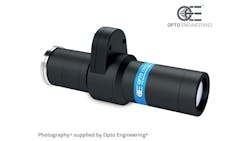
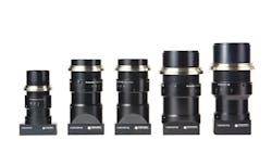
The TCEL series (Figure 1), by Opto Engineering® (Mantova, Italy; www.opto-e.com), features a combination of telecentric optics and liquid lens technology, allowing users to significantly increase DOF. This is particularly important for small fields of view due to the proportionality of the DOF with the magnification. The optical design of TCEL lenses ensures optical performance in terms of telecentricity and distortion throughout the entire operating range, making them suitable for applications including electronic and semiconductor segments, automotive, and pharmaceutical.
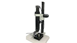
According to Marco Pigozzi, Senior Global Sales Manager, Optotune (Dietikon, Switzerland; www.optotune.com), fixed focal length lenses have been extensively used in the machine vision industry, however they often have a limited depth of field, which is challenging for several applications. To solve this challenge, “Optotune has developed optimized integrated solutions, which are integrating focus tunable lenses, to support a wide range of applications,” Pigozzi says. “The key advantages of the focus tunable lens technology are: extended depth of field, fast focus within milliseconds, long lifetime, and high accuracy.”
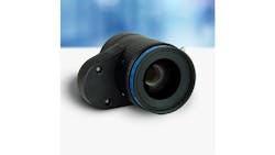
Optotune’s ELM series portfolio supports S-mount and C-mount cameras up to a sensor size of 1.1 in. with focal lengths ranging from 5 to 300 mm. In particular, its ELM-25-2.8-18-C lens (Figure 2) features focal length of 25 mm, F# of 2.8, and pixel size of 2.4 µm; accommodates a sensor size of 1.1 in.; supports C-mount cameras; and can be used in a number of applications such as robotic vision, barcode reading, package sorting, and bottle inspection.
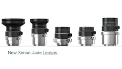
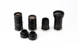
The Schneider Optics Xenon Jade series (Figure 3), optimized for use in machine vision applications, is a set of lenses focusing on new sensors like the Sony Pregius S™-Generation 4.
TECHSPEC® LH Series Fixed Focal Length Lenses (Figure 4), from Edmund Optics, are ultra-high resolution, large format lenses designed for 120 MPixel sensors in APS-H format. The LH Series supports the 2.2 μm pixel size featured on the Canon 120MP CMOS sensor. These lenses work with APS-H sensors (35.5 mm diagonal) and on larger 35 mm full frame sensors (43.3 mm diagonal). F-Mount and TFL-II Mount versions are available.
The MPT Series 45 MPixel 1.4” Machine Vision Lenses (Figure 5) from Computar Optics Group are compact, lightweight, and engineered to optimize the capabilities of the latest industrial CMOS image sensors. The floating design provides performance at any working distance. The lenses feature high-level aberration correction and centering/alignment technology. The positioning of the high refractive index glass and low partial dispersion glass at crucial locations, the field curvature, and astigmatism are comprehensively corrected.
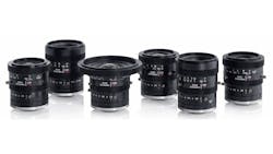
Carl Zeiss recently released a new Dimension® lens family (Figure 6) specifically for industrial C-mount applications. These lenses are designed for image sensors up to 4/3 in. format and offer a compact, lightweight, and rugged aluminum housing. The Dimension® family consists of six focal lengths ranging from 8 to 50 mm. With the help of the innovative adjustment mechanism, it is easy to compensate for tolerances at the camera mount. In addition to the C-mount’s stable screw connection, locking screws on the focus and aperture rings guarantee a high degree of stability and ensure that the settings remain in the correct position. These lenses can resolve pixel sizes down to 2.0 µm. Low distortion (< 2%) combined with high contrast images from center to edge make these lenses suitable for challenging industrial applications.
FUJIFILM North America’s Fujinon CF-ZA-1S series (Figure 7) supports large high-resolution 1.1 in. format image sensors with 2.5 µm pixel pitch (equivalent to 23 MPixel). The relative illumination reaches up to above 90%, and a clear image can be obtained from the image center to the peripheral area.
The VEO lens series (Figure 8), which Vieworks and Schneider-Kreuznach codeveloped, is optimized for the sensitivity and light wavelengths of Vieworks TDI cameras. The camera specification was carefully considered from the very first stage of the lens design process to make the combination of the VTDI camera and VEO lens perform the best.
Navitar has recently introduced a Super Wide Angle 4K Imaging Lens (Figure 9) designed to offer microscopy customers an alternative for low magnification high resolution imaging in industrial and life science applications. The system achieves a wide FOV to capture more of the sample with each image—enabling faster object detection and increasing throughput.
VS Technology’s VS-HX series 8K Resolution Large Format Fixed Focal Length Lens (Figure 10) supports Image circles up to ϕ32 mm and 2.74 µm pixel resolution for enhanced clarity. This lens series is designed for the demands of high speed and high resolution applications. Its compact and lightweight design allows this series to be installed in limited spaces.
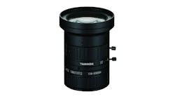
Tamron’s industrial-use fixed-focal lens, the SMA11F12 (Figure 11), features high spectral transmittance over a wide band from the visible-light to the SWIR bands while the focus-shift is suppressed to an absolute minimum over the entire band. The lens offers significant reduction of focus-shift in between the visible-light and the SWIR bands corresponding to the wavelength of 400 to 1700 nm. Tamron’s proprietary lens coating technology assures approximately 80% constant spectrum transmittance over the whole spectrum from the visible-light to the SWIR band. The lens is compatible with imagers with a pixel pitch of 5 µm.
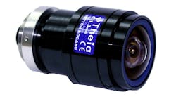
Theia’s MY125 C-mount lens (Figure 12) provides up to a 135-degree horizontal FOV without barrel distortion. It uses Theia’s patented Linear Optical Technology® to correct barrel distortion optically without software and the latency inherent in software correction. The MY125 lens provides 200 lp/mm resolution performance in visible light with a minimum object distance of 10 cm and a pan focus distance from 0.3 m to infinity. It is for up to 1/2.5 in. sensors, in manual or DC auto iris and also is available in CS-mount (SY125). “This lens would be a good choice for sensors up to 1/2.5 in. and sensor resolution up to 5 MPixels,” adds Van Landingham.
Archer OpTx offers the PerfectLens™ SIVA (System Imaging Vision Assembly) Series (Figure 13) that functions very near the computer design model, offering high resolution wide angle (250/300 lp/mm, 10 MPixel sensor), high resolution narrow angle (350 lp/mm, 15 MPixel sensor) and high-resolution (225 lp/mm, 3 MPixel sensor) camera lenses.
Words of Wisdom
Fitzgerald suggests consulting with experts on the topic to get started. “Having a discussion with experts can help you specify the correct camera and lens combinations for your application,” he says. “Also, evaluating cameras and lenses recommended by an expert can help remove possible missteps when building a successful solution.”
There is a lot to consider when selecting lenses for your vision system, none the least of which is figuring out what type of lens your application requires. Keeping the entire system in mind will pay off. “It is very important for us to discuss the customer’s whole system and environment because there are some external effects that cause vision/image system errors,” says Sugahara.
“Make sure that the object to be looked at is well understood” comments Sischka. “The edge case scenarios are always the hardest ones to solve, so knowing exactly where the threshold between a failure and a pass is can make a huge impact on the success of a system. Additionally, try to understand all of the system level constraints and try not to make compromises everywhere else with the assumption that ‘the optics can make up for it.’ ”
Torigoe adds, “Evaluate what is actually necessary for a specific project or purpose and choose based on that. Don’t overspend unnecessarily. Just because the lens specs ‘look good’ on paper does not always mean the results will also ‘look good.’ One option may be less expensive than another from the onset, but if it does not do what is required—and do that consistently over time—it will actually cost more in the long run. Be aware of what you actually need, what you ultimately end up with, and be sure that they are the same.”
Lorin adds, “Beware of over-specifying a lens. We would encourage everyone to read about MTF in digital systems to learn about what you can reasonably expect from a digital imaging system. You cannot see anything with a single pixel, so there’s no point in specifying MTF there. Even two pixels is questionable, depending on how you’re processing the data.”
Again, timing is everything, and specifying the lens early in the process will save time and money later. According to Van Landingham, “Lens selection can often be an afterthought, but considering the lens requirements in the beginning is highly recommended. Work to pair the lens to a camera with the correct resolution, sensor size, and pixel size and study how all these factors affect performance in the specific application—this can help avoid delays and costly mistakes.” Sekiya adds, “Specify the camera first and then the lens. Make sure to use a lens with good MTF, or contrast. The better the MTF, the better the contrast in the image, which makes for optimized resolution. Next, make certain the lens has enough resolution for your camera. Always verify that the lens’s pixel pitch is equal to or smaller than the pixel pitch on the camera. And finally, verify that the lens’s format size is equal to or greater than the camera’s sensor format.”
Dyas adds, “There is still much misconception about optics. Do not over or undervalue the lens. I like this old adage: ‘Your system is only as good as the glass you use.’ ”
Companies Mentioned
Archer OpTx, Inc.
Rockwall, TX, USA
Carl Zeiss
White Plains, NY, USA
Computar Optics Group
Cary, NC, USA
Edmund Optics
Barrington, NJ, USA
FUJIFILM North America Corporation
Wayne, NJ, USA
Navitar
Rochester, NY, USA
Opto Engineering®
Mantova, Italy
Optotune
Dietikon, Switzerland
Schneider Optics
Hauppauge, New York, USA
Tamron USA, Inc.
Commack, NY, USA
Theia Technologies
Wilsonville, OR, USA
Vieworks Co., Ltd.
The Republic of Korea
VS Technology
Tokyo, Japan
About the Author
Chris Mc Loone
Editor in Chief
Former Editor in Chief Chris Mc Loone joined the Vision Systems Design team as editor in chief in 2021. Chris has been in B2B media for over 25 years. During his tenure at VSD, he covered machine vision and imaging from numerous angles, including application stories, technology trends, industry news, market updates, and new products.
