If you have worked in machine vision a bit, you have likely used area cameras, and you may be aware of line scan cameras that are useful in certain circumstances. You likely have been given the impression that line scan imaging requires an extremely intense light source. This article examines line scan lighting requirements by comparing it with area camera lighting. This provides you a perspective on illumination for line scan imaging that enables you to make a better decision on when to use line scan imaging.
Area and Line Scan Image Sensor/Camera Review
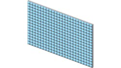
Images from area cameras are the most familiar because of photography, television, webcams, and similar devices as well as wide use in most other imaging situations. An area camera consists of a two-dimensional array of pixels (light sensors) having some number of rows and columns (Figure 1). The range of rows and columns is typically specified by the product of the two and expressed as megapixels. Common values range from 0.3 MPixels (640 × 480 pixels) to 20 MPixels (5472 × 3648 pixels). Sizes up to 150 MPixels (14,204 × 10,652 pixels) are available but at extremely high cost.
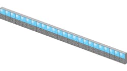
Images from line scan cameras consist of only one row of pixels (Figure 2). The number of pixels in a row typically ranges from 2 048 up to 32,768. Usually, a two-dimensional image is created by moving the part under the camera or the camera over the part.
If parts are in continuous motion, a line scan camera might be an easier and less costly option than one area camera or multiple area cameras. Consider finding 0.5-mm defects on a 1-meter wide web. If four pixels need to span the defect for reliable detection, then it takes 8000 pixels to span the web. Line scan imaging can meet this requirement with only one camera. Area scan imaging will need multiple cameras and to stitch together the images.
For stationary parts where more than, say, 5000 pixels are needed to span the part, it may be more economical to use line scan imaging together with motion control to move the camera over the part rather than one or more area cameras.
Illumination Requirement Comparison
We need to refine terminology and replace the colloquial term intensity, which has a specific and different technical meaning, with irradiance. Irradiance is the density of incident light power or power per unit area. We can convert from power to energy by multiplying power by time; in this case the exposure time of the camera.
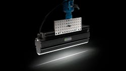
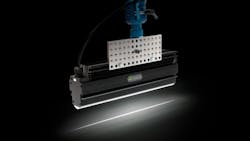
The generally accepted characteristic of line scan imaging is that it needs higher irradiance (Figure 3). “Higher” implies a comparison—in this case, a comparison with an area camera. Let’s examine this closer.
Suppose you have two cameras. One is a line scan camera with 1000 pixels in its line. The other is an area camera with an image resolution of 1000 × 1000 pixels. We’ll assume the pixels are equal in sensitivity. Further, assume the area camera has an exposure time of 30 ms. The line-scan camera will be moved over the scene to acquire 1000 scan lines resulting in an image of 1000 × 1000 pixels, and the time to scan over the area will be 30 ms. This means the exposure time for each individual line is 30 µs. It also means that the irradiance for the line scan camera needs to be 1000 times greater than the area camera. However, the area camera illumination must cover an area 1000 time larger than the line scan illumination. So, it would seem the required illumination power is the same for both cameras.
Our comparison of line scan and area scan image sensors then appears to change to somewhat favor line scan sensors.
Let’s look at another case with the same two cameras except this time the part is moving past the cameras. In machine vision, best practice is to limit blur because of movement to one pixel. For the line scan camera, this is its characteristic when imaging a moving part—the blur is one scan line or pixel in the direction of travel. We can use the same illumination for the line scan camera as we did in the previous example because the exposure time is still 30 µs. However, for the area camera, its exposure time must be reduced from 30 ms to 30 µs—the same as the line-scan camera—to control blur.
In this example, the irradiance of the area camera illumination must be equal to that for the line scan camera, except it must still cover the whole field of view. So, the area camera requires 1000 times the light power of the line scan camera.
This need for increased power for the area camera can be offset by pulsing (strobing) the light source for perhaps 30 µs. This means the light energy—the product of light power and exposure time—for the line scan camera, where only a line is illuminated continuously, and the light energy for the area camera, where the area camera is illuminated with 1000 times the light power but for only 1000th the time, are the same.
Let’s examine some other factors that affect the results above.
It is very difficult, optically, to focus light into a thin line. Most commercial line light sources focus a row of LEDs into a line using a cylindrical lens. Without going into detail, there is an optical principle called étendue, one of those very inconvenient laws of physics, which states that projected light power is affected by both the area and solid angle and that whatever you do, you cannot increase étendue from the light source; you can only maintain or decrease it.
The light sources, usually LEDs, have an area and a large solid angle of light emission. The line of light wants to cover a very narrow, and therefore very small, area at a much more limited solid angle. Therefore, it is impossible to illuminate a thin narrow line without discarding much of the light energy unless the light source is extremely close to the line to increase the solid angle to compensate for the reduced area. Available line light sources, while fairly tightly focused, tend to cover a much broader line than the line scan camera images—much of the incident light energy is unused.
Étendue also affects area camera illumination, but usually to a lesser degree than line scan illumination.
When an LED light source is pulsed or strobed for a very short duration relative to the time between light pulses, it can often be overdriven up to 10 times and produces much more light power than a steady state light. This has the potential to make area camera illumination more effective.
One assumption made at the beginning of this article is that the pixels (sensing elements) of the area image sensor and the line scan image sensor were equal. Of course, in the real world, this isn’t the way things work. Line scan image sensors typically have larger pixels than area cameras along with a fill factor approaching 100% (the percentage of the pixel’s area that is sensitive to light).
The larger pixel along with a larger full well capacity to store the photogenerated charge means that line scan images typically have lower noise than area camera images.
Because of circuitry that must be included with each pixel, most CMOS area image sensors have only a fraction of the area allocated to each pixel, perhaps around 30%. Microlenses incorporated over each pixel tend to compensate for the limited fill factor to some degree. The effective fill factor might approach 60%. There are CMOS area image sensors made with back side illumination (BSI) where the fill factor approaches 100%. BSI image sensors are more expensive than conventional area image sensors.
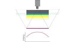
Another common observation about line scan imaging is the nonuniformity of the response. As shown in the bottom graph in Figure 4, when the line scan camera images a scene, it is usually bright in the center and falls off toward the edges. While a small part of the falloff can be attributed to the lens, the bigger cause is that the light source doesn’t extend clear across the illumination “W.” If the width of the light source included the dashed area or larger, then the nonuniformity is greatly reduced. Often, this is not practical for physical reasons. The same effect can be observed in area camera imaging. Using flat-field correction is one way to compensate to correct for this effect.
Magnification’s Effect on Illumination Requirements
There is another consideration, not necessarily obvious, related to light energy. Energy is just power times time—for cameras, this is the exposure time. For full exposure, each pixel of an image sensor, whether it is an area camera or a line scan camera, requires a certain energy. This energy is independent of the area imaged. As a camera’s field of view decreases, that is, magnification increases, and as long as the effective f-number of the lens is constant, the total light power illuminating the scene must stay constant–the irradiance must increase. So, smaller fields of view require proportionally higher irradiance.
For line scan cameras with small lines of view, it becomes almost impractical to raise the irradiance to the needed level.
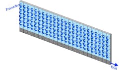
There is a line scan technique that mitigates the need for the extreme irradiance. It’s called time delay and integration (TDI). The TDI sensor has multiple line scan sensors side by side. The number of lines of sensing elements can range from a dozen to a couple hundred (Figure 5). At the end of each exposure, the exposed image is shifted from one line to the next toward the output line. Only the final line is read out. The photogenerated charges accumulate line after line until reaching the output. In effect, you get a multiplier of 12 to 200 depending on the number of parallel lines. This gives the TDI sensor the function of a line scan sensor with much increased sensitivity. So, it tends to mitigate the difficulty of getting all the light power into a very thin line or needing extreme irradiance.
In conclusion, line scan cameras do require a light source providing higher irradiance than is required for area cameras. This is not because line scan cameras are less sensitive but because of a law of optical physics. When the irradiance tends toward impractical levels, the TDI camera offers a potential solution.
Perry West is Founder and President of Automated Vision Systems, Inc.
About the Author

Perry West
Founder and President
Perry C. West is founder and president of Automated Vision Systems, Inc., a leading consulting firm in the field of machine vision. His machine vision experience spans more than 30 years and includes system design and development, software development of both general purpose and application specific software packages, optical engineering for both lighting and imaging, camera and interface design, education and training, manufacturing management, engineering management, and marketing studies. He earned his BSEE at the University of California at Berkeley, and is a past President of the Machine Vision Association of SME Among his awards are the MVA/SME Chairman’s Award for 1990, and the 2003 Automated Imaging Association’s annual Achievement Award.
