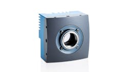
High-Speed Camera Helps Determine Melt Flow Characters in Laser Cutting Machines
Unterschleißheim, Germany—Laser flame cutting of metal plates is a well-established industrial process that uses oxygen as an assist gas instead of inert gases to increase process capabilities. However, this process is characterized by a much narrower window of optimal process parameters when comparing to cutting processes involving an inert assist gas, such as laser fusion cutting with nitrogen. Determining those parameters is critical to productivity and accuracy.
An experimental setup facilitating systematic in-process observation of trim-cut testing was recently introduced by researchers in the Department of Mechanical Engineering at Katholieke Universiteit in Leuven, Belgium1. Integrated into a commercially-available laser cutting machine, the setup was able to accurately determine the optimal trim-cut parameters for laser flame cutting of mild steel based on melt flow dynamics. Melt flow characteristics have an oversized influence on cut quality, especially for fiber lasers, and need to be collected accurately. Characteristics were visualized by means of a Mikrotron EoSens CL camera set at a frame rate of 15,000 frames-per-second (fps) which allowed estimating the velocity of the melt flow inside the cutting front at 5 meters per second (m/s).
Experiments were performed on an industrial-grade fiber laser cutting machine with a 4-kW IPG Ytterbium multimode laser source emitting at 1.07-µm wavelength with Gaussian intensity distribution. The laser beam was delivered from a 100-µm core optical fiber with a numerical aperture of 0.12 into a Precitec ProCutter laser head equipped with a 200-mm focusing lens and a 100-mm collimation lens. Setup featured two parallel linear rail systems, one that held a carriage with the camera and the other that held a replacement edge carriage. The camera carriage is driven directly by the laser head via the connection structure, thus removing the need for additional linear actuators and synchronization. A belt transmission connects the camera carriage to the replacement edge carriage to permit not only an inversion of moving direction but also different relative velocities of the laser head and the replacement edge according to the used gear ratio.
Sample observations were performed with the Mikrotron EoSens MC1362 Camera Link high-speed camera. The camera's region of interest (ROI) was set to 80 × 145 pixels with an exposure time to 2 µs, enabling a frame rate of 15,000 fps. Magnification of 0.1 made it possible to size the whole sample thickness to the ROI. In order to avoid overexposure of excessively bright parts of the image, dynamic range adjustment (DRA) was applied. DRA changes the sensor transfer characteristics in order to provide a more detailed view at the extreme contrast that, in the studied cases, appears between the cold cutting edge and the molten material of the cutting front.
A protective window installed in front of the Mikrotron camera shields the optical components from splashing molten metal. In addition, an OD 6 notch filter with a bandwidth of 1064 ± 36 nm was placed before the camera lens to remove the scattered and reflected laser radiation, which is significantly higher than the thermal radiation from the process zone and can damage the camera sensor. Moreover, an additional bandpass filter with a wavelength range of 650 ± 20 nm was located next to the notch filter to decrease the process radiation intensity. A Keyence Digital Microscope VHX-6000 was used for high-resolution imaging of cut edge profiles, while surface roughness was measured by a Mitutoyo Formtracer CS-3200 using a Gaussian filter.
In this specific test, researchers used their set-up to find the optimal parameters for trim cutting 15mm mild steel, determining that to be a replacement edge distance of 500µm and a trim-cut width of 50% as the most suitable. However, researchers believe their testing tool provides great opportunities to enhance the future understanding of the broader process, such as the origin of quality deterioration, and may help to identify solutions for process improvement.
Learn more about Mikrotron high-speed cameras at www.mikrotron.de/en
1. Trim-cut technique for analysis of melt flow dynamics in industrial laser cutting machine Levichev N., Rodrigues G.C., Garcia A.T., Duflou J.R. (2020) Procedia CIRP, 95, pp. 858-863.
