What Are Athermalized Machine Vision Lenses?
Standard, off-the-shelf imaging lenses developed for machine vision or imaging systems perform well in temperature-controlled environments and in applications where temperatures shift only slightly. However, in high-performance vision systems subjected to extreme or wide shifts in temperature, athermalized imaging lenses are a good choice because they help minimize temperature-dependent performance changes.
What is Athermalization?
Athermalization refers to the process by which an optomechanical system becomes rugged enough to withstand extreme or changing temperatures. It also describes the optomechanical system that underwent the process.
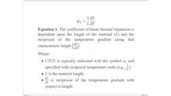
Matter expands and contracts in response to temperature changes. This change in material size (Figure 1) can be described by the coefficient of thermal expansion (CTE). Equation 1 shows the coefficient of linear thermal expansion (CLTE), as opposed to the coefficients of area or volumetric expansion—all of which are referred to as CTE. Linear CTE or CLTE is the most commonly used form.
This helps explain why high-performance vision systems subjected to extreme or wide shifts in temperature require athermalized imaging lenses to minimize temperature-dependent performance changes.
Because imaging assemblies consist of a series of glass elements seated in groups that are housed within a larger metal barrel, there are additional effects that need to be considered when designing a machine vision system for extreme temperature changes.
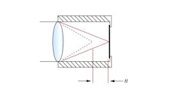
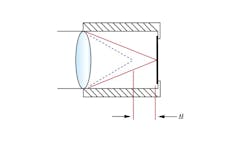
Thermal defocus is directly related to both the change in refractive index and changing material dimensions over the operational temperature range of a lens system.
For example, a heated lens barrel will expand and separate the vertex-to-vertex spacing of the elements, allowing for some decenter or roll. This will cause the index of refraction of the glass materials to change, all combining to affect the focus position of the lens system as the temperature changes (Figure 2). Some of these additional factors include changes to optical aberrations, focal length, tip, tilt, and decenter.
Types of Athermalization
Athermalization to minimize focal length change over temperature can be achieved actively or passively. These terms refer to the type of compensatory actions required to implement adjustments to maintain acceptable operating conditions.
Passive athermalization is achieved by exploiting both the thermo-optic effect (TOE) and the differences of material CTEs by building the materials into the design of the optical system in such a way that they compensate for both the refractive index and dimensional changes. By combining different materials, focal length can be fixed as temperature changes over a particular range of temperatures without the need for additional user intervention or outside electromechanical support. Because there are fewer technical components with passive athermalization, this type of athermalization produces products that are typically better suited for space or weight-constrained applications.
Active athermalization can involve the use of additional support hardware or enclosures that may either “actively” compensate or correct the focus of the lens system or provide a heating or cooling capability to maintain the lens system at a design focal length. Both of these examples require a feedback control loop for the active system to stabilize the optics at the desired system focus position, or temperature set point, respectively. While active athermalization makes use of less exotic optical materials and is more robust for use in application environments with larger operating temperature ranges, this type of athermalization is typically bulkier, more expensive to implement, and requires a form of power to be supplied.
Metrology
When it comes to verifying the performance of an athermalized lens, lens design software such as Zemax (Canonsburg, PA, USA) and CODE V from Synopsys (Sunnyvale, CA, USA), in conjunction with CAD software, are often used to simulate or model optomechanical and optothermal performance of imaging lenses. Though simulating thermal effects does provide some insight about how a lens design will respond to thermal changes, these simulations are quite limited in scope and are often inaccurate.
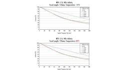
Imaging lens manufacturers that specify performance metrics for given temperature ranges should be able to guarantee such performance with data collected from testing lenses in state-of-the-art thermal performance test chambers. While the ambient temperature of the test chamber is varied, a test bench records the change in one or more of the critical operating parameters. For most imaging lenses, including fixed focal length lenses, the most useful parameter obtained is the modulation transfer function (MTF). MTF is the optical transfer function that correlates how the contrast of the image that the lens creates changes at different spatial frequencies or resolutions. Test stations similar to Figure 4 are used to measure the MTF of an imaging lens during the manufacturing process. The MTF curve allows the end user to predict lens performance at any temperature within the designated range. Analysis of additional parameters for other lens types are sometimes needed such as the change in chief ray angle for telecentric lenses.
Applications for Athermalized Imaging Lenses
Applications where an athermalized imaging lens is ideally suited include aerospace imaging with unmanned aerial vehicles (UAVs) or drones, surveillance, and manufacturing in harsh factory environments. For example, UAVs can be subjected to significant changes in temperature as they travel higher into the atmosphere to perform inspections. UAV drones are increasing in popularity in the agricultural industry for the inspection of crop health and yield.
Factory automation has always been one of the most dominant markets for machine vision, and some manufacturing settings contain environmental factors that that can damage standard-type imaging system components. Besides extreme temperatures, these factors include shock, vibration, high-temperature and high-pressure water from washdown. Inspection for welding or laser material processing applications can also expose an imaging system to harsh temperatures as well; thus, experts recommend athermalized systems.The demand for imaging systems in harsh environments is growing and enforces stricter performance requirements for these systems. Extreme and changing temperatures require vision systems that are desensitized to or shielded from temperature changes with design compensation. These types of athermalization requirements push past the limits of standard off-the-shelf imaging lenses and often mean custom solutions. Athermalization can be applied to imaging lenses in varying degrees of protection, some of which are more costly than others and require more testing time than standard lenses. For these reasons, it is typically easier to consider athermalization for custom imaging lenses designed from scratch than to retrofit standard or off-the-shelf imaging lenses. For all application circumstances, it is important for engineers to understand all the system-level application requirements and to maintain close and clear communication with the lens manufacturer. By following these protocols, they’ll ensure that the custom lens meets the performance specifications.
About the Author

Rebecca Charboneau
Rebecca Charboneau is an optical engineer at Edmund Optics (Barrington, NJ, USA). She is part of Edmund Optics’ Engineering Leadership Program and is currently working with the imaging team at the company’s Cherry Hill, N.J. office. She joined Edmund Optics in 2021 and has been working closely with both machine vision and life science customers to provide them with custom optical solutions based around their system needs.


