Vision tests microshutter arrays
Off-the-shelf components inspect MEMS array for infrared imaging in space.
By C. G. Masi, Contributing Editor
A microshutter array-a microelectromechanical system (MEMS) device that acts as a dynamic aperture mask-enables astronomers to observe hundreds of different objects in a single field of view. System-integrator Mink Hollow Systems is helping test optical components such as the microshutter array for the NASA James Webb Space Telescope (JWST) by writing the software and helping with system integration (see “James Webb Space Telescope,” p. 88). The company is a subcontractor for Sigma Space, which is the lead contractor for the microshutter-array-test program on the JWST.
“We’re trying to characterize the flight array-in other words, we’re stressing the array,” says David McAndrew, test engineer at Mink Hollow Systems. “When you open and close the shutters multiple times, they eventually start to break. We want to provide an automated test system that will actuate the array X number of times. For this case, we’re testing on the order of 2 million cycles.”
While the microshutter array must be kept in a vacuum at low temperature to mimic the ambient conditions in interplanetary space, the test equipment is designed for laboratory conditions and must be kept out of the environmental chamber. The difficulty, therefore, is to test the components inside the chamber with tools located outside.
Testing inside/instruments outside
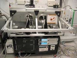
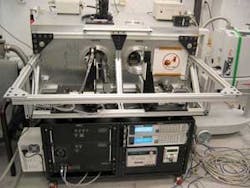
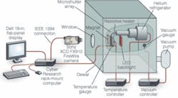
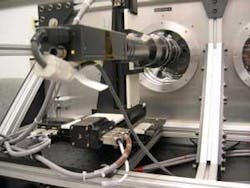
The environmental chamber is a large vacuum/temperature shield called a Dewar flask (see Fig. 1). The Dewar consists of a vacuum-tight box with a highly reflective interior. The vacuum not only mimics the gas pressure in interplanetary space, but minimizes convective heat transport between the warm enclosure and the cold array under test. Aluminizing the enclosure’s interior minimizes radiative coupling of thermal energy. So, the only significant thermal contact to the array is by conduction, which is used to cool the array.
To achieve the array’s roughly 30 K operating temperature, the engineers use a helium refrigerator. The refrigerator operates on the same thermodynamic cycle as a home refrigerator or air conditioner, but the working fluid is helium, rather than refrigerant-12 (R-12). Although helium is less effective as a refrigerant than R-12, its boiling temperature is much lower-less than 5 K. The refrigerator’s business end (called the cold finger) sticks through the vacuum chamber wall and achieves a temperature of approximately 10 K. The array attaches to the cold finger by two straps, which provide a known thermal resistance. Passing electrical current through resistors built onto the array mounting plate warms it up to its operating temperature by balancing the electrical power input with the heat flow through the straps to the cold finger (see Fig. 2 on p. 87).
The test-measurement results consist of a statistical record of microshutter failures as a function of the number of open/close cycles. An open/close cycle starts with all shutters closed. The system applies the hold-open voltage to all shutters, then mechanically sweeps a permanent magnet across the array using a mechanism similar to what will be installed in the flight instrument. The magnetic force pulls all of the shutters open, where they are held by the electrostatic forces. The cycle ends when removing the hold-open voltage allows all of the shutters to spring closed.
The host computer cycles the shutters every quarter-second for a preset number of cycles. On the last cycle, it triggers acquisition of two images during the cycle. The first image captures a view of the entire array with all of the shutters held open. The second shows the array when all of the shutters are closed. After acquiring these images, the system goes back to cycling the shutters open and closed for another series of cycles.
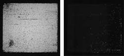
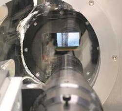
The vision system sees the microshutter array backlit by a diffuse LED illuminator. Shutters that fail in a stuck-closed position appear as black spots on the image during the “open” part of the cycle (see Fig. 3). Stuck-open shutters appear as white spots on the nominally “closed” part of the cycle. Image-analysis software analyzes these images to locate and count each stuck-open and stuck-closed shutter. The test software then archives these data to provide trend and history analysis at the end of the test. A full test typically consists of applying 1 million to 2 million open/close cycles over a few days, with images captured every 10 thousand to 100 thousand cycles.
To acquire a set of images takes about 30 s because the camera cannot fit the entire array in one field of view with the resolution needed. Instead,x and y stages move the camera in a raster pattern over the array, taking individual frames at each raster position (see Fig. 4). Software stitches these frames together to form the full high-resolution image.
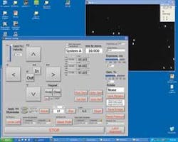
The system also has a manual mode that allows NASA scientists to move the camera by hand (see Fig. 5). They can move it to frame any desired array region and zoom in or out to highlight only those shutters of interest. While navigating, they view a live image on the system monitor and can capture images for later processing (see Fig. 6)
The Sony FireWire XCD-SX910 camera and Newmark Systems NLS4-4 motorized stages were never built to work in the Dewar’s 10-7 Torr vacuum, so they must stay outside and view the array through a 5-in.-diameter window in the vacuum wall. The window is an optical-quality flat made of BK7 glass and coated to minimize radiative heating of the array from the warmth outside.
Because the camera links to the computer via an IEEE 1394 (FireWire) interface, no frame grabber is needed. The computer is a rack-mounted unit manufactured by Cyber Research. It has a 3-GHz Pentium 4 processor with 1 Gbit of RAM. The user interface includes a Dell 19-in. flat-panel monitor, also mounted on the rack.
The test software acquires the images directly through a National Instruments IEEE 1394 driver. McAndrew wrote the test software for controlling the test sequence using National Instruments LabVIEW environment.
Engineers program a particular automated test using a text-based script. The user interface provides dialog boxes that allow the user to set various parameters for a test step. For example, one script line might tell the computer to perform 10,000 open/close cycles. The next step might tell it to acquire an image mosaic with the shutters held open, including all the imaging parameters, such as how many frames are needed for the mosaic. The next line might tell the computer to allow all the shutters to close, and so forth. After the user fills in the dialog box and clicks “Save,” the software creates the script line and appends it to the script file. Users do not normally work with the individual script files, but, since they are stored in ASCII format, users can view and modify them in any text editor, such as Windows Notepad.
Providing information
The test system is now in operation at the NASA Goddard Space Flight Center, where engineers are using it to improve their microshutter-array fabrication process. “They want to see trends,” says McAndrew. “When the shutters break, do they break open or do they break closed, and after how many iterations? They get a lot of that information just by qualitatively looking at the image mosaics and zooming in to certain areas.”
The test program has already provided two important pieces of information. First, when shutter elements break, they tend to do so early in their life. This means that if the shutters are working after several hundred thousand cycles, there’s a high probability that they will continue to work indefinitely. As a result, once they learn to fabricate an array that lasts through a limited life test in the Dewar, they can fly that array with confidence that it will last through the service life of the JWST.
Second, the impact of the shutter closing can cause breakage. With this information, NASA engineers devised a method of closing the shutters more slowly by deactivating the voltage while the magnet is still in front of the shutter. The magnetic force keeps the shutter from slamming shut. As the magnet moves away, the torsion force slowly overcomes the gradually decreasing magnetic force, allowing the shutter to close gently.
NASA’s engineers are also developing image-processing algorithms to postprocess the images. This software will go through all the images to determine what percent stayed open and what percent stayed closed and report what happened to that array throughout the test. It will make it easier to quantify trends over long-life tests, providing better characterization of array failure mechanisms. This will help help NASA monitor the health of the JWST during its service life.
James Webb Space Telescope
The James Webb Space Telescope (JWST) is a large, infrared (IR) optimized space telescope scheduled for launch by NASA in August 2011. The JWST is designed to study the earliest galaxies and some of the first stars formed after the “Big Bang.” These early objects have a high redshift from vantage point of Earth, meaning that the best observations for these objects are available in the IR. So instruments on the JWST will be designed to work primarily in the IR range, with some capability in the visible range. The telescope’s primary mirror will be 6.5 m in diameter.
All objects emit IR light based on their surface temperatures. To avoid swamping the very faint astronomical signals with radiation from the telescope, the telescope and its instruments must be very cold. To help maintain its low temperature, the JWST has a large shield that blocks the light from the Sun, Earth, and Moon, which otherwise would heat up the telescope and interfere with the observations.
To work properly, JWST must be in an orbit where all three of these objects are in approximately the same direction. The most convenient point is the second Lagrange point (L2) of the sun-Earth system, a semistable point in the gravitational potential around the Sun and Earth. The combined gravitational forces of the sun and the Earth can almost hold a spacecraft at this point, and it takes relatively little rocket thrust to keep the spacecraft near L2. The cold and stable temperature environment of the L2 point will allow JWST to make the very sensitive IR observations needed. -C. G. M.
Company Info
Cyber Research
Branford, CT, USA
www.cyberresearch.com
Dell
Round Rock, TX, USA
www.dell.com
Edmund Industrial Optics
Barrington, NJ, USA
www.edmundoptics.com
Mink Hollow Systems
Highland, MD, USA
www.minkhollowsystems.com
NASA Goddard Space Flight Center
Greenbelt, MD, USA
www.nasa.gov/goddard
National Instruments
Austin, TX, USA
www.ni.com
Newmark Systems
Mission Viejo, CA, USA
www.newmarksystems.com
Sigma Space
Lanham, MD, USA
www.sigmaspace.com
Sony Electronics
Park Ridge, NJ, USA
www.sony.com/videocameras
Thermos LLC
Rolling Meadows, IL, USA
www.thermos.com
