Vision system sorts ball bearings
Andrew Wilson, Editor, [email protected]
Tasked with the problem of automatically sorting different sizes of ball bearings, four undergraduate students at Texas A&M University (College Station, TX, USA; www.tamu.edu) headed by senior electrical-engineering student Scott Savage have developed a system using off-the-shelf drives, lighting, and vision. The system is used to sort three different types of ball bearings of 5/8-, 9/16-, and 1/2-in. diameter.
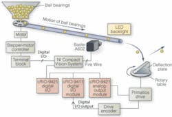
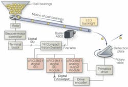
Rather than use a conveyor belt to transport the ball bearings along a production line, the system uses a gravity-fed system (see figure on p. 29). Ball bearings pass through the field of view of a vision system and onto a deflection plate located on a rotary table. As the balls pass over the field of view of the system’s camera, a blob-detection algorithm detects the size of each of the balls, and the angle of the plate is adjusted accordingly. As the balls fall onto the plate, they are deflected into three individual bins. In this way, the system can sort individual ball bearings in real time as they pass though the system.
Individual ball bearings of various sizes are presented to the system in a large hopper. To allow individual ball bearings to travel through the hopper, Savage and his colleagues fabricated a circular plate that was rotated using a stepper motor from Micro Mo (Clearwater, FL, USA; www.micromo.com). Carefully fabricating a specific number of circular openings around the circumference of the plate and controlling the speed of the stepper motor allowed individual balls to fall though the circular openings at a specified rate.
“Interestingly,” says Savage, “perhaps the most difficult part of the design was not programming the vision system or controlling the motion of the deflection plate; it was controlling the dispensing motor. Ball bearings are heavy and because the number of ball bearings in the hopper varies with time, the force on the rotating plate also varies. Because of this, the torque needed to turn the motor needs to compensate for the changing weight, and it is necessary to slowly ramp up and down the current to the motor to compensate.”
To accomplish this, digital I/O lines from an NI CVS-1456 Compact Vision System from National Instruments (Austin, TX, USA; www.ni.com) were used to control the digital inputs of the stepper motor controller. “Because of the high speed and dynamic control required by the system,” says Savage, “it was necessary to customize the FPGA embedded in the Compact Vision System with LabVIEW FPGA to perform the motion control.”
This same Compact Vision System was used to control the image-processing and the sorting mechanism of the system. To digitize the ball bearings as they travel along the gravity feeder, the system uses an A602 camera from Basler (Ahrensburg, Germany; www.baslerweb.com). Interfaced to the NI Compact Vision System though a FireWire interface, the camera runs at 100 frames/s at resolutions of 320 × 240 pixels. To capture a silhouette of each of the ball bearings, a red LED backlight from Advanced Illumination (Rochester, VT, USA; www.advancedillumination.com) is used.
After images are captured, a blob analysis is performed on each image using LabVIEW and NI’s vision development module to determine its diameter. Results of whether each ball bearing is small, medium, or large are then output from the Compact Vision System over three separate 24-V triggers sent from the terminal block to an eight-channel Compact RIO-based cRIO-9421 digital input module, also from National Instruments.
To properly deflect the ball bearings, an angled plate is placed at 45° on a rotary stage from Primatics (Tangent, OR, USA; www.primatics.com). To power the embedded drive of the stage and provide an encoder input to the rotary stage two CompactRIO modules are used. While the cRIO-9263 provides a ±10-V output to the drive itself, a cRIO-9411 monitors the TTL output from an encoder on the high-speed rotary stage. The three 24-V I/O signals from the Compact Vision System are input to a cRIO-9241 data-acquisition module. These signals are then interpreted by the system’s cRIO host controller, and the proper positioning of the defection plate is sent via the cRIO-9411 to the motor encoder. Depending on the position of this plate, ball bearings falling from the hopper though the vision system are properly deflected into three separate bins.

