Explore the Fundamentals of Machine Vision: Part I
Machine-vision systems are composed of myriad components that include cameras, frame grabbers, lighting, optics and lenses, processors, software, and displays. While simple machine-vision systems can identify 2-D or 3-D barcodes, more sophisticated systems can ensure inspected parts meet specific tolerances, have been assembled correctly, and are free from defects.
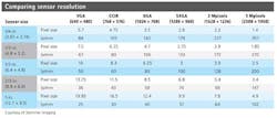
Many machine-vision systems employ cameras that can employ a number of different types of image sensors (see table). However, to determine the achievable resolution of cameras, it is important to understand the number of line pairs per millimeter (lp/mm) that the sensor can resolve rather than the number of available pixels.
In a typical 2588 × 1958-pixel, 5-Mpixel imager, for example, a pixel size of 1.4 µm2 provides a resolution of 357 lp/mm, while a 640 × 480-pixel VGA imager with a 5.7µm2 pixel size sports a resolution of 88 lp/mm. For the same size of imager, smaller pixel features will allow more line pairs per millimeter to be resolved.
If a particular image sensor contains 3 µm2 pixels, for example, then the minimum theoretical feature size that can be resolved in the image is 6 µm due to Nyquist's sampling theory. In practice, however, this is unachievable because every lens will exhibit some form of aberration.
Grayscale images are often stored with 8 bits per pixel, which provides 256 different shades of gray. While dark features in an image take on a low numeric values, lighter pixels take on higher values. This is convenient since a single pixel can then be represented by a single byte.
Choosing cameras
Traditionally, machine-vision systems have employed cameras that transfer captured images over an interface such as USB 3.0, Gigabit Ethernet, FireWire, Camera Link, or CoaXPress to a PC-based system.
Today, smart cameras that integrate machine-vision lighting, image capture, and processing tasks are proving inexpensive alternatives for automated vision tasks such as reading barcodes or detecting the presence or absence of parts. Although the performance of the processors found in smart cameras may be sufficient to handle these tasks, more complex or higher-speed functions will require additional processing power.
Performance is not the only issue. System integrators must also determine what software is supported and how cameras can be interfaced to external devices. Although many smart cameras are deployed in parts presence/absence tasks, for example, other applications may require the cameras to interface to displays that show an operator the captured image and the results of the image analysis performed.
Many smart cameras run dedicated or proprietary operating systems on their processors; others run commercial operating systems such as Linux or Unix. As such, they can run any PC-based software package.
Illuminating parts
By employing the correct machine-vision lighting, features within images can be repeatedly captured at high contrast. If the lighting is incorrectly specified, the success, reliability, repeatability, and ease of use of the machine-vision system are at risk. To ensure the correct types of lighting are employed, designers should consult with lighting manufacturers or develop an image lighting lab to test various lighting options.
Although fluorescent, fiber-driven halogen, and xenon strobe light sources are often employed in machine-vision systems, LED lighting is beginning to replace these technologies because of its uniformity, long life, and stability. Available in a variety of colors, LED lighting can also be strobed—a feature that proves useful in high-speed machine-vision applications.
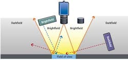
Aside from the type of lighting, one of the most important factors that will determine how an image appears is the angle at which the light falls on the object to be inspected. Two of the most popular means to illuminate an object are darkfield and brightfield illumination (see Fig. 1).
Darkfield illumination is produced by using low-angle lighting. On an object with a perfectly flat, mirror-smooth surface, all the light emanating from the object will fall outside the field of view of the camera. The surface of the object will then appear dark, while light from any part of the surface that may exhibit a defect or a scratch will be captured by the camera.
Brightfield illumination is the opposite of darkfield illumination. Here, the lighting is placed above the part to be imaged. Hence the light reflected from the object will fall within the field of view of the imager. In a brightfield lighting configuration, any discontinuity on the surface will reflect light away from the imager and appear dark. Thus, the technique is used to illuminate diffuse nonreflective objects.
Color effects
If an application demands the use of a color camera, white light will be required to illuminate the part to be inspected. If the colors of a part must be differentiated, then a white light that produces an equal spectrum over all wavelengths will enable the colors in the image to be analyzed.
Colors in images can also be discerned by monochrome cameras. To do so depends on choosing the appropriate lighting to illuminate the image (see Fig. 2). The images on the top appear as they would to the human eye, while the bottom images shows how a monochrome camera might see them.
To light this image, three different colors of light have been used: a 600-nm red light (left), a white light (center), and a 520-nm light (right). To produce the best contrast for this image, it is best to use a green light since green is complementary to red. This contrast can then be easily discerned using a monochrome camera. To wash out the red, it would be more suitable to illuminate the sign with a red light. If the image itself was multicolored, and no one particular color in it needed to be highly discriminated, a white light would be a more appropriate choice.
In Part II of this series on fundamentals, David Dechow will describe a number of image-processing algorithms commonly used in machine-vision systems.
Vision Systems Articles Archives


