Color Cameras Turn Down the Heat in Boiler Inspection
Declan McCabe
The inspection of boilers has been a manual process in the past, susceptible to human error. Although errors can be detected by testing the assembled products, the test stations can become a bottleneck that restricts productivity. Such a problem was faced by Ideal Heating, a company that called upon ALPHR Technology to implement an automated inspection line.
Rather than installing a traditional production line where products are inspected for defects after assembly is complete, a "zero defects forward" approach was taken. This involves inspecting a product after each major step in the assembly process so defects can be recognized and corrected at each stage.
With a forward-inspecting system, reworking an error is usually easy, fast, and inexpensive. In addition, no time or money is wasted on completing the assembly of a defective product that, in all probability, will ultimately need to be disassembled and then reassembled.
Online assembly
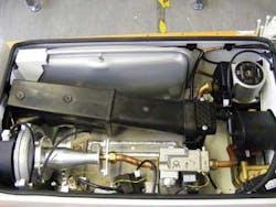
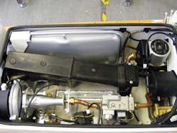
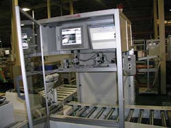
During the online assembly process, boilers placed on nylon trays are transported on conveyors between four vision-based inspection stations (see Fig. 1). These stations are installed at critical points along the production line and control the movement of the conveyor so that no boiler is transported to the next inspection station until it has met all of the inspection criteria.
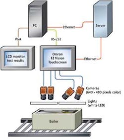
Each of the inspection stations has a common system architecture that comprises one or more 640 × 480-pixel color cameras from Omron Electronics Ltd. interfaced to one or more Omron FZ4 Vision Touchscreen systems (see Fig. 2). The touchscreen systems are bundled with a library of image-processing software that can be deployed to sequentially perform a variety of functions on the images captured by the cameras.
The touchscreen systems are also interfaced to a Windows PC over an RS-232 serial interface. This enables Visual Basic programs running on the PC to issue commands to the touchscreen systems to capture data from the cameras and perform specific vision inspection routines.
Test results from each inspection are then returned to the PC where they are displayed on an LCD VGA monitor. The results are also stored locally on disk in a SQL database, as well as transferred to a server where the results from the tests from all the workstations can be collated.
Gas injectors
At the first of the inspection stations, a check is performed to ensure that a gas injector of the correct size has been fitted to the boiler. A barcode reader from Datalogic first scans a barcode on the boiler. The data are then used to determine the model of the boiler and the size of the injector that should be fitted to it.
To measure the size of the injector, the boiler assembly's baseplate is illuminated by a pair of white LEDs from Advanced illumination. An image of the boiler assembly with the injector sufficiently contrasted within it is then captured using a vertically mounted Omron 640 × 480-pixel FZ4 camera connected via a Camera Link interface to an Omron FZ4 Vision Touchscreen controller.
Image-processing software running on the touchscreen controller first locates the position of the part within the image, after which an edge detection tool is used to locate the top and bottom edges of the injector. The size of the injector can be calculated by measuring these edges (see Fig. 3).
Tolerance measurements specified in the Visual Basic software on the PC are transferred to the vision system over RS-232 before the automated inspection. By comparing the size of the injector with data captured from the barcode reader, the system determines whether the correct injector has been fitted to the boiler.
If the boiler passes the first inspection test, it is then transferred to a second station where a PCB controller board is fitted to the boiler. The second inspection station then checks the wiring loom and mechanical fixtures inside the boiler assembly to ensure that they have been properly installed and connected.
Prior to this assembly, the PCB controller board is also inspected by an offline vision system that employs three Omron FZ cameras linked over a Camera Link interface to an Omron FZ4 Vision Touchscreen controller. Here, one of the cameras captures an image of the grommet of the mains lead, while the second and third capture images of the connectors and the mains terminal strip. Data captured by the cameras is analyzed by a classification tool running on the touchscreen controller to determine whether the PCB should pass the offline inspection before being fitted to the boiler.
Wiring and harnesses
At the second online station, the internal parts of the boiler are illuminated directly using four 12-in. white LED line lights from Advanced illumination, while four Omron color cameras mounted at angles capture images of specific sections of the internal features of the boiler. As in the previous online inspection station, the cameras are also interfaced to a Vision Touchscreen, PC, server, and LCD monitor.
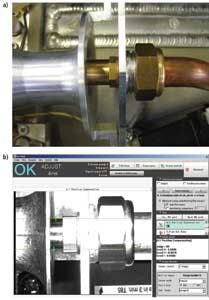
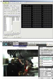
Prior to the inspection process, the touchscreen system must be trained to identify the connectors and mechanical fittings and that they have been fitted to the boiler correctly (see Fig. 4a). Images of correct and incorrect parts, as well as those that have been assembled correctly and incorrectly, are captured offline by an Omron FZ-SC camera and stored in the touchscreen system.
Due to potential variations in the manual assembly process, a particular wire in an assembly, for example, could have a number of different orientations. For that reason, the system must be trained to identify numerous alternative correct configurations as well as those that are incorrect.
Because of the variety of boilers that Ideal produces, the image classifier in the FZ system must identify all the components in all the models of boilers that are produced, and all their power variants. In this way, the classification tool can identify which parts may have been incorrectly inserted in a specific model of boiler, whether a component that was supposed to be installed in one boiler was assembled in another, and which component was installed.
Having been trained, the inline system captures images of the boiler from the four cameras (see Fig. 4b). Next, a Visual Basic script instructs the touchscreen system to run through a sequence of programs on each of the camera images to identify the parts. Pass/fail results from the classification procedure are then returned to the PC over the RS-232 interface and stored in the SQL database.
Lids and packaging
If the boiler passes the second inspection test, the boiler is fired up and tested to determine whether it is working correctly. If it is, the boiler then passes down the conveyor where a third vision inspection system checks the lid.
At this station, four Omron color cameras capture images of specific parts of the lid. Specifically, one camera captures an image of the Ideal badge on the boiler, a second the LCD, a third the last digit of the badge that indicates which variant of the boiler it is, and a fourth the model details found on the boiler door.
Having passed this test, the boiler is packaged into a cardboard container into which an instruction manual and a toolset are inserted. It is then transferred to a fourth inspection station where one 640 × 480-pixel color camera captures an image of a code on the literature pack to ensure that the correct instructions have been packed with the boiler. A second camera captures an image of the toolset box, plastic housing, and metal plate that is used to commission the boiler.
At both the lid inspection and packaging inspection stations, the image classification tool on the Omron FZ4 vision system is used to identify the parts and ensure that they are present and correct, and the results returned to the PC and remote server (see Fig. 5).
Modifications are being undertaken by ALPHR Technology in order to achieve a more future-proof inspection system for Ideal Heating, taking into consideration the diversity of boiler parts and the capabilities of system components (see "Percolating plans for future system design" on page 28).
Declan McCabe is an application engineer with ALPHR Technology (www.alphrtechnology.co.uk).
Percolating plans for future system design
As the number of boiler variants produced by Ideal Heating has increased, the original vision systems developed by ALPHR Technology have been upgraded to inspect diverse components. The original wiring inspection station has been upgraded to support eight cameras, rather than four. Because the Omron FZ4 controller can only interface to four Camera Link cameras, this necessitated a second FZ4 system to handle the task.
The updated vision system will capture images of the boiler harness using a single 2-Mpixel Omron camera mounted on the end of an Omron five-axis robot, which will obviate the need for making any adjustments to the eight cameras on the existing wiring inspection station to accommodate new models, ultimately producing a more flexible system that can be programmed to capture images of the internal parts of each boiler produced by the company.
In future lines, the lid and packaging stations will use Omron's PC-based GigE cameras, allowing eight cameras to be used without additional FZ controllers. The software interface will remain the same as it is on the FZ controller but will run on a PC instead.
Company Info
Advanced illumination
www.advancedillumination.com
ALPHR Technology
www.alphrtechnology.co.uk
Datalogic
www.datalogic.com
Ideal Heating
www.idealheating.com
Omron Electronics Ltd.
http://industrial.omron.co.uk
Vision Systems Articles Archives
