FPOAs speed flat-field correction
Andrew Wilson, Editor, [email protected]
Flat-field correction is used to adjust image-sensor output data to ensure that constant intensity images generate constant pixel values at various levels of image intensity. This process addresses three types of pixel-based nonuniformities: gain, dark current offset, and defective pixels. To rectify these nonuniformities, both a calibration and correction process must be performed. The calibration process determines the correction factors for pixel gain and offset and generates a defective pixel map. The correction process calculates an appropriate value for nonuniform pixels.
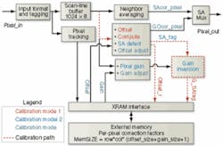
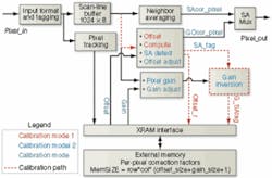
Field-programmable object arrays (FPOAs) from MathStar (Minneapolis, MN, USA; www.mathstar.com) can perform both calibration and real-time correction required in flat-field correction (see figure). FPOAs are programmed at the level where objects can be arithmetic logic units, multiply accumulators, or register files that can be clocked at up to 1 GHz. Adjacent objects are interconnected via nearest neighbors, and distant objects are interconnected via party lines.
To perform flat-field calibration involves recording the sensor’s dark-current offset values and calculating the offset-correction factor for each pixel using Newton-Raphson or binary division.Offset calibration requires measuring each pixel’s dark-current value. With the imaging aperture closed, an image is captured and each pixel value stored in memory as the offset correction factor. Gain calibration uses an external bright field image source, with a well-characterized intensity distribution across the sensor array, which is captured by the camera under test. If the test image is known and constant, gain calibration is straightforward. If the starting image is defined by the valuec at each pixel, and the captured image pixel values is defined by matrix P, then cG = P, and the calibration process is used to solve for the gain matrix G.
During normal operation of the sensor, gain and offset-correction factors are applied to each pixel to achieve a uniform response. This is achieved by subtracting a value from each pixel that corresponds to that pixel’s dark current value and multiplying each pixel by an inverse gain coefficient, so that the effective gain for all sensor pixels is normalized to a single value.
Defective pixel analysis determines if a pixel is stuck at a constant value or is sufficiently nonresponsive that its output value is outside of the acceptable gain and offset correction envelope. Defective pixel mapping is performed simultaneously with the gain and offset calibration. If its dark current value or measured gain factor of each pixel is outside the desired range, then a marker is set in the defective pixel map corresponding to the location of the defective pixel.
Once the correction factors for gain and dark current offset have been calculated for each pixel, they are stored in the FPOA memory and applied to each pixel output value during camera operation. This removes the sensor nonuniformities from the image generated by the camera.
Defective pixels can either be replaced by the value of a nearest neighbor or by a new value, derived by interpolating the surrounding nearest-neighbor values. Here, each defective pixel is replaced by an average of the eight surrounding nearest-neighbor values. For a 1024 × 1024 image using 16-bit pixel values, 2 kbytes of memory is required for each line of the image.
The maximum throughput can scale up to 4 Gpixels/s. This is bounded by the external memory (XRAM) bandwidth, which is as high as 8 Gword/s. Although the gain and offset correction factors are typically 12 and 6 bits, respectively, the architecture uses 16-bit precision for gain correction, offset correction, and pixel data to avoid any overhead logic for packing and unpacking the data. This pixel rate is equivalent to a very large 8k × 8k image sensor operating at 60 samples/s. This flat-field error correction implementation requires anywhere from 13 to 22 objects in an FPOA, depending on the pixel rate. Current FPOA devices from MathStar provide 400 total objects.

