Lens design targets flat-panel inspection
Checking pixels on large LCDs requires adaptation of lenses to linescan cameras.
By Jeremy Govier
Manufacturers of large flat-screen LCD-based displays must ensure that no inactive or dead pixels are present before the panels are assembled into finished computer terminals or television displays. To do this inspection as cost-effectively as possible, LCD manufacturers are using very large 12k × 1 CCD imagers coupled with custom-built lenses.
These linescan cameras operate by digitizing linear images as they pass under the camera. In a typical LCD application, LCD panels with 5 million pixels are moved under the field of view of multiple cameras so that in each pass, each camera can digitize up to 12k pixels. During inspection, all the pixels of the display are energized as the display moves past the camera. To pass inspection, every LCD pixel has to glow at full brightness; no dead pixels are allowed.
To develop an optical system that it could attach to Dalsa’s 12k linescan camera, Edmund Optics was faced with developing a new lens for a machine-vision system integrator. Since such large-format CCD array presents 12,288 7-µm sq pixels arranged in a line 86 mm long, available lenses could not maintain the required optical performance over the entire sensor.
While the integrator considered using a large-format photographic lens, it was discovered that while photographic lenses for cameras larger than 2.25-in. format are designed to create images larger than 80-mm diagonal, their performance is not adequate for machine-vision applications. They fail two important performance parameters: even illumination and low distortion.
Photographic images concentrate their information content near the center of the frame, and photographic lens designers allow the illumination level to fall off toward the field edge (vignetting) and allow aberrations and distortion to increase. While these compromises are unnoticeable in photographic applications, optical performance at the field edges in machine-vision applications is every bit as important as it is in the center.
Lens design
When inspecting 5-µm pixels on a LCD that moves past the camera, the light intensity that activates each sensor pixel determines how fast the part can move past the sensor. Since the light source is the LCD panel, the only way to increase the inspection speed was to increase lens speed.
After performing a study, it was found that the preferred lens speed would be considerably faster than ƒ/5.6. Captured images needed to be flat, of low distortion, and free of vignetting over a 90-mm-wide field. A minimum 0.1 MTF at 100 lp/mm in object space was also required.
In addition, no standard mounting system currently exists to support such large CCD sensors. To perform the LCD inspection, each 7-µm CCD pixel needed to view a 5-µm object (an individual LCD pixel). This defined the lens magnification required: 0.007 mm/0.005 mm = 1.4x. Given the 86-mm CCD array length, the camera could view an 86/1.4 = 61.5-mm-wide strip along the LCD. To inspect wider LCDs requires either multiple passes or multiple cameras.
Since the camera must image red, green, and blue pixels, the lens needs to be color-corrected across the entire visible region. And, as the camera needed to resolve 5 µm on the object and 7 µm on the image, a design criterion of 10% contrast at 72 lp/mm for the MTF was set.
Edmund realized ƒ/5.6 would be too slow, and a few trial designs were built to determine how low the f-number could become while maintaining acceptable performance. To accomplish this, two ray-tracing packages, Code V from Optical Research Associates and Zemax from Zemax Development Corporation, were used to test the trial designs with different lens speeds and analyze their MTF.
Increasing the aperture to lower the f-number (that is, increase the lens speed) works against lens resolution, increasing aberrations and blurring the image. This makes the design very demanding, requiring a multielement lens design and tight tolerances. After many optimization trials, an ƒ/4 design performed as needed within achievable manufacturing tolerances.
The difference between ƒ/5.6 and ƒ/4 makes is significant. Because image brightness varies inversely with the square of the f-number, an ƒ/4 lens produces an image twice as bright as an ƒ/5.6 lens, allowing parts to move twice as fast past the lens.
Mounting issues
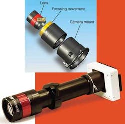
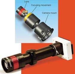
Dalsa’s 12k line-sensor is 3.5 times larger than a C-mount and twice as large as a F-mount. To avoid the mount’s edges blocking outer rays passing to the large sensor required bolting the lens to a large grid of M3x0.5 screw holes-much larger than more common mounts such as F-mount, M42, and C-mount.
The mount consists of two components, the course and fine focus movements, and the appropriate camera mount (see figure on p. 31). The final prototype is compatible with 12k pixel cameras and can produce up to 100-lp/mm object-space resolution 0.1 MTF. Able to accommodate 7-µm pixels and sensors up to 90 mm, the low-distortion lens accommodates any linescan application. Its ƒ/4 aperture provides twice the image brightness of an ƒ/5.6 lens.
Jeremy Govier is director of design services, Edmund Optics (Barrington, NJ, USA; www.edmundoptics.com).
Company Info
Dalsa
Waterloo, ON, Canada
www.dalsa.com
Edmund Optics
Barrington, NJ, USA
www.edmundoptics.com
Optical Research Associates
Pasadena, CA, USA
www.opticalres.com
Redlake
Tucson, AZ, USA
www.redlake.com
Zeemax Development Corporation
Bellevue, WA, USA
www.zemax.com

