Vision system speeds engine-block inspection
Ten smart cameras, off-the-shelf lighting, and software allow engine-block oil passages to be rapidly inspected.
By Andrew Wilson, Editor
In the automotive industry, lost-foam casting is often used for creating one or more copies of a three-dimensional engine block. In the lost-foam casting method, an expanded polystyrene replica of the part being cast is placed in a holder and loose sand is placed around it. Molten aluminum is poured through a funnel into the sand, where the hot metal melts and displaces the foam pattern. The molten metal evaporates to form the finished part. Unlike conventional sand-casting methods, the lost-foam process allows more complex and detailed passages and features to be cast directly into the part.
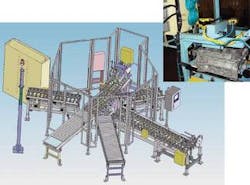
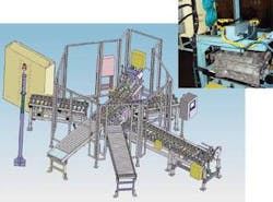
These cylinder-block castings incorporate many internal features that reduce machining costs, including high-pressure oil passages, oil drain-backs, crankcase air passages, and coolant jackets and channels. After the casting process is completed, the engine block must be cleaned, and the many passage holes that guide oil through the engine must be inspected for debris that may have formed during casting or cleaning. To do this, a major automotive manufacturer called upon Rogers Associates Machine Tool Corporation (RAMTC) to develop an automated system capable of inspecting the oil passages (see Fig. 1).
“Using machine vision to solve this problem was not our initial approach,” says Mark Ely, a senior controls engineer at RAMTC. “Although we realized that we required a noncontact method of examining the oil passages within the engine blocks, it was thought that coupling the passage holes with an air- or fluid-based system and then measuring the air or fluid pressure could be used to test whether a specific passage was blocked. “Unfortunately,” says Ely, “this would have necessitated coupling the engine block with multiple air- or fluid-based systems and would have taken a long time to both set up and dismantle.”
Passage holes
Instead, Ely and his colleagues opted to build a system with ten smart cameras, an off-the-shelf PLC, display controller, and lighting equipment (see Fig. 2). It was necessary to inspect ten oil-passage holes after the engine block was held stationary in a specially designed fixture developed by RAMTC. What added to the complexity of the design were the three types of passage holes that needed to be inspected. “While simple short through-holes could be relatively easily lit and imaged,” says Ely, “others were blind through-holes from the main bearing, the balance shaft cavity, or the top of the engine block to cavities that joined other cross-holes.”
Because of these numerous types of through- and blind-holes, it was critical to choose the correct system to illuminate the engine block. “To light the backside of the five short through-holes,” says Ely, “a 6-in. EL193 backlight strip from Advanced Illumination provided enough luminous 660-nm red LED light intensity for the cameras located on the opposite side of the hole to obtain a high-quality image.”
Illuminating the blind through-holes proved more complicated. Unlike simple through-holes, the blind holes can transverse complex passages through the engine block. “Thus,” says Ely, “light illuminating one side of these holes will be attenuated as the light traverses the engine block.” To obtain an image of the passage through these holes, a higher-illumination LED spotlight must be used. For the five blind-holes, RAMTC used three HLV-27-R red LED spotlights from CCS America. While one spotlight illuminated three of the blind through-holes, the two most complex through-holes required an individual spotlight for each task.
To image both the through- and blind-holes, RAMTC mounted ten In-Sight 5000 smart cameras from Cognex around the fixture holding the engine block. These cameras feature a 1/4-in. 640 × 480 CCD, one optoisolated acquisition trigger input, and two built-in, high-speed outputs. “To obtain the required depth of focus, these cameras were fitted with both 25- and 50-mm C-mount lenses from Tamron, depending on the hole to be inspected. “In this application,” says Ely, we found that these lenses were ‘telecentric enough’ to produce the images we required.”
Image features
Depending on the type of hole to be inspected, specific features of images captured from the ten cameras were captured and analyzed and a pass/fail decision made upon the result. To program each of the cameras, Ely used Cognex In-Sight Explorer vision-sensor software. “Using the In-Sight spreadsheet supplied with the program,” says Ely, “each of the sensors could be configured with drag-and-drop vision tools and graphics palette, using a Windows XP-like interface to access camera images and security settings.” This spreadsheet tool includes specialized functions, such as blob-analysis and measurement tools, that allow relatively complex applications to be developed without writing any code.
Although some cameras were mounted perpendicular to the oil passages, images of other more complex blind passages were imaged using cameras placed at an angle to the holes. “Because of this,” says Ely, “it was necessary to perform a number of machine-vision functions on each of the images to determine whether the passageways were blocked.” These functions included measuring the intensity of light as it emerged, the area and perimeter of the light, its height-to-width ratio, and its on-axis angle. “While all of these analysis tools provide important information,” says Ely, “they are weighted differently, with intensity and blob area providing 80% of the most important data.”
Once images are captured by each individual camera, both the dark features of the engine block, the outline of the balance shaft of the engine, and the light emerging from the oil passages can be seen (see Fig. 3). To calculate the intensity of this light, the blob tool within the In-Sight software is first programmed to locate the blob of light.
“In the more difficult to image holes,” says Ely, “this may appear as an oblong light.” Once the blob is located, its area is measured and the number of pixels over a specific preset intensity is determined. This ensures that the camera has located the lit area and not some other object in the field of view of the camera. “Should this hole be blocked,” Ely says, “both the area and intensity of this blob will be reduced significantly.”
At the same time, the In-Sight software calculates the perimeter of the light. “Should any blockage occur in the oil passageway,” says Ely,” this measurement can be reduced and provides an extra level of confidence to the operator.” Similarly, taking measurements of both the height-to-width ratio and on-axis angle of the light blob ensures that an unexpected blockage is not present and that the camera has not moved during the inspection process.
System interfaces
After image measurements are made, they are weighted and a pass/fail decision is made in each of the ten In-Sight 5000 cameras. This pass/fail trigger information is transferred directly to a Modicon Quantum 140-CPU-113-03 PLC from Schneider Electric using the cameras digital I/O lines. In turn, this PLC is interfaced to a PanelMate 1700 Power Series from Eaton Electrical over a Modbus interface.
“Because this intelligent operator interface features an embedded PC, the unit can directly control the PLC using the PanelMate Power Pro configuration software. This can also be used for higher-level functions such as machine setup, diagnostics, alarming, and developing trending and custom graphics functions,” says Ely.
Once an engine block has passed all the necessary inspections, it must be marked and moved to the next inspection station. To do this, a 43S inkjet printer from Videojet Technologies is interfaced to the system’s PLC, and, under control of the Eaton PanelMate, the host is programmed to mark a specific code onto the engine block. Should an engine block pass all the tests, a ten-digit code (one character for each cameras) is printed on the engine block along with an operator code and a black strip that indicates to a downstream operator that the engine block has passed inspection.
Should an engine block pass some of the tests and fail others, only the number corresponding to the successful camera inspection is printed on the block. In this way, the engine block can be manually inspected and reworked and again passed through the machine vision system. In such cases, the process is repeated and numbers corresponding to successful camera inspections inserted in the code.
After each part is marked, it must be moved onto a rotary table where it can be transferred to another production stage. To do this, RAMTC developed a roller conveyor that is controlled with the host system’s PLC using the PanelMate host operator interface. After marking, each part is automatically transferred to this stage, where it is moved via a conveyor to another operator station.
Features, advantages, benefits
Although its inspection system has been developed especially for a major automotive manufacturer, Rogers Associates Machine Tool Corporation president Jeff McFaddan sees opportunities in other areas of the automotive industry, including automated inspection of transmissions, braking systems, and bearings. With this in mind, the company made its first trade-show appearance in June at the ATX East show (New York, NY, USA). “In addition to offering engine-block inspection systems such as this to other automotive manufacturers,” says McFaddan, “we are also looking at opportunities in aerospace and general manufacturing industries.”
Company Info
null


