Vision helps robot wire lighting fixtures
Winn Hardin, Contributing Editor
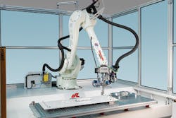
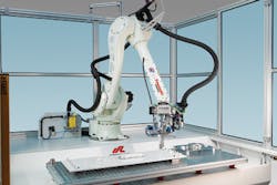
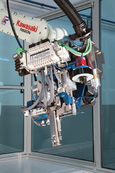
Wiring components in electrical appliances such as lighting modules is a dull and repetitive task that requires absolute precision as a single defective contact could cause an appliance to malfunction. Since robots can perform the same wiring operation faster and more accurately than a human being, engineers at System Robot Automazione (SRA; Visano, Italy; www.systemrobot.it), have developed a number of such systems for the lighting industry. The company's latest offering-a robotic wiring system called Syndy-makes use of a RS20N 6-axis robot from Kawasaki (Wixom, MI, USA; www.kawasakirobotics.com) whose arm is fitted with a custom built wiring head (Figure 1).
Equipped with two wiring fingers, the wiring head can roll out electric cable, cut it, strip ends and connect them fully automatically to the components in the fixture. It can wire horizontal and 90° push-in terminals and insulation-displacement connector (IDC) terminals during the same cycle. This capability enables the robot to equip an electrical module with many different standard components such as lamp holders, terminal blocks, ballasts and terminals of LED drivers and accessories.
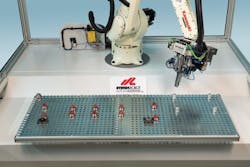
Prior to wiring, an unwired electrical fixture is manually placed onto a universal pallet in front of the robot. The pallet sports a matrix of holes into which both centering pins with magnetic heads and reference pins, are fitted. The centering pins ensure that an operator locates each unique lighting fixture accurately onto the pallet at a predetermined position, while the reference pins ensure that the robot can locate it accurately prior to wiring (Figure 2).
The robot is programmed to perform the wiring of the fixture through the use of a teach pendant that is used to manipulate the robot through the steps of each wiring task. In use, an operator moves the robot to each component on the fixture that needs to be wired, after which the path of the robot and the position and type of the component is stored in the system.
Vision locates components
To ensure that the robot can accurately locate and wire each component on the fixture, the operator must ensure that the fixture is precisely positioned on the universal pallet. This is especially important when wiring Printed Circuit Boards (PCBs) or Surface Mounted Devices (SMDs) into LED luminaries where the system must locate the connectors on the PCBs or SMDs within a tolerance of +/- 0.2mm.
In cases where accurate placement cannot be guaranteed, the Syndy wiring robot can be fitted with an optional vision system to assist with the task. The vision system features a Manta G-046B 780 x 580 pixel monochrome camera from Allied Vision Technologies (Ahrensburg, Germany; www.alliedvisiontec.com) that is fitted with a 16mm lens from Tuss Vision (Tokyo, Japan; www.tussvision.com) and a green band-pass filter from Midwest Optical Systems (Palatine IL, USA; www.midopt.com) - see Figure 3.
The fixture is illuminated with a green LED flash ring from Shanghai BMT Automation (Shanghai, China, www.bmt.sh.cn/en). The lighting and camera filter combination enables high contrast images of the components in the fixture to be captured regardless of varying lighting conditions, which is important since the robot is not enclosed in a cabinet with controlled lighting.
The first step involves locating the components on the fixture within the vision camera's field of view. In the case of the Syndy robot, a specific reference fixture is first presented to the system and an image of it captured by the monochrome camera. The image of the fixture is then transferred over a Gigabit Ethernet interface to a 32-bit Intel Celeron M dual processor based industrial PC.
Once the image has been acquired by the PC, Vision Pro PatMax geometric pattern matching software from Cognex (Natick, MA, USA; www.cognex.com) is used to identify and then teach the system the location and the geometry of the objects to be wired within the fixture with reference to the pins on the universal pallet. A software macro can then be chosen from a set of custom built software routines to instruct the robot as to which type of wiring needs to be performed at each point. The data associated with the specific fixture is then used to create a master reference.
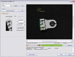
When the system is used to inspect an unwired fixture, a new image of the fixture is captured by the camera and transferred to the PC. PatMax software then recognizes the location and the geometry of the parts to be wired and compares these to the master reference. If the system detects any deviations from the master reference, a visual indicator alerts an operator, and any anomalies are displayed on a flat panel display (Figure 4). Such visual indicators provide a way for an operator to see which of the parts on a fixture have been incorrectly assembled or positioned on the fixture out of any pre-defined tolerances.
The system will not allow the wiring process to begin until any anomalies have been resolved by the operator, either by removing the fixture to reinsert a component or to align it correctly on the universal pallet. Hence, the preliminary vision inspection step ensures that the robot arm will accurately move to preset positions in the fixture prior to performing any wiring operations.
Software tools
Because the Cognex VisionPro software suite has a .NET programming interface, engineers at SRA can access the geometric pattern matching software tools using Visual Studio Software. This enabled them to integrate their own TS-Vision software development suite with the Cognex software to build a customized system.
While the Cognex VisionPro pattern matching software performs an important role in identifying the components on the fixture, no less important is the operation performed by the TS-Vision software. This manages image acquisition and controls the aperture of the camera to ensure brightness and contrast uniformity of captured images.
The software can also analyze the position of each component on the fixture with reference to its theoretical position during run time and adjust the wiring program accordingly. In this way, the robot can adapt to any variances in the module's geometry that may occur during the manufacturing process.
The nature of the inspection process executed by the vision system is dependent on the type of part in the fixture to be inspected. For the most part, conventional socket connectors inside a punched steel electrical fixture are usually within an acceptable tolerance, so the vision system is only used as a means to check if the connectors are inserted correctly. In other cases, however, the inspection process needs to be more rigorous. When inspecting an LED module, for example, all the contact points on the LED need to be checked to ensure that they are in the correct position in the assembly before they can be wired by the robot.
To enable a lighting manufacturer to perform the appropriate vision inspection task, the TS-Vision software provides a lighting manufacturer with a set of functions that enable the models of the components to be wired to be stored in the system where they can be edited, if so desired. Using the software, a manufacturer can choose to modify the tolerances that are acceptable when comparing a component on the image with those stored in the reference master in the database. This feature enables certain components, especially on fixtures such as fluorescent lamps, to be wired by the robot even if they have not been perfectly located on a fixture.
One of the most important features of the TS-Vision software is that it enables the co-ordinates of the features identified by the vision software to be communicated to the robot. To do so, the coordinates and head orientation data of each component to be wired is passed from the PC to the Kawasaki robot over an Ethernet interface via a UDP protocol. Once the robot receives this data, it moves into position over the components to be wired, and performs the wiring task with a repeatability of +/-0.05mm.
Future challenges
The wiring process can be automated further through the use of off-line 3D graphical software, which allows an operator to import and manage drawings of the light-fittings. Having imported a drawing, an operator can not only create a wiring path from it, but also virtually locate the components on the fixture from the database on the PC.
Having done so, the TS-Vision software can generate a program to automatically wire the components on the light fitting. By importing a 3D drawing of each light-fitting, the software also enables an operator to simulate the wiring cycle while performing cycle time calculations and detecting any potential collisions of the robot head.
The Syndy system is available in various configurations depending on the number and the nature of the tasks to be performed by the robot. The choice of configuration depends on the production capacity and the nature of the light-fitting assembly process that the manufacturer intends to automate. The system can also be fitted with a station that can carry out tests on the wired luminaries to measure the insulating resistance, earth circuit resistance and dielectric strength of the components in the fixture.
Currently, system developers at SRA are making improvements to the system to accommodate a more diverse range of connectors and modules used by manufacturers who assemble electrical fixtures. In addition, the company is working with electrical goods makers to ensure that Syndy systems can be integrated into fully automated production processes where components are automatically assembled before being placed and wired into the fixtures.
Company information
Allied Vision Technologies
Ahrensburg, Germany
www.alliedvisiontec.com
Cognex
Natick, MA, USA
www.cognex.com
Kawasaki
Wixom, MI, USA
www.kawasakirobotics.com
Midwest Optical Systems
Palatine, IL, USA
www.midopt.com
Shanghai BMT Automation
Shanghai, China
www.bmt.sh.cn/en
System Robot Automazione (SRA)
Visano, Italy
www.systemrobot.it
Tuss Vision
Tokyo, Japan
www.tussvision.com
Vision Systems Articles Archives
