Multi-camera vision system inspects engine rings
Russ Butchart
Third-party suppliers of automotive components must ensure that their products are carefully inspected before they are shipped to their customers for assembly. Often, these suppliers produce a large number of parts with numerous part variations. In producing metal alloy engine rings, for example, one manufacturer recently needed to upgrade their existing imaging system to meet a higher throughput and an increasingly large number of product types. To meet the quality control criteria demanded, each engine component must be inspected for small defects on all the surfaces of the part while providing an accurate and repeatable means of measurement.
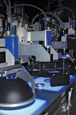
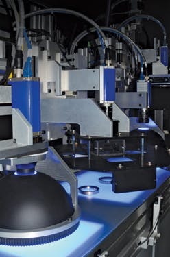
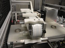
To meet these challenges, Puffin Automation was tasked with creating a system that would inspect defects as small as 0.008in on all four surfaces of the engine ring, have a changeover time of less than 1 min, be capable of inspecting 1,500 individual parts varying from 1-3 in in diameter and 0.125 to 0.75 in in height and still be easy to operate (Figure 1). Since material handling and changeover can also be expensive and complicated with such large part variations, serious challenges were faced in designing a system to handle the large variation of parts and still inspect all four surfaces.
In the past, the customer had employed line scan cameras to inspect the inner and outer surfaces of the part. To accomplish this, each part was rotated in front of line scan cameras using large rotary dials and tooling which were costly to set up and maintain. To image the parts, complex lighting techniques were also required making the system complex from a material handling perspective.
Six stations
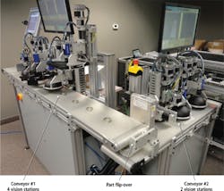
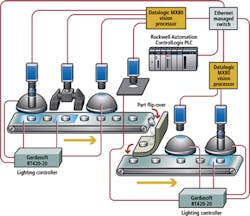
This system developed by Puffin Automation consists of two conveyors with translucent belting and a flip-over device between them. A simple part alignment device was used at the beginning of each conveyor to properly center the parts under multiple inspection and illumination stations that employed area array smart cameras.
To perform the task of inspecting the parts, six inspection stations incorporating two M Series industrial processors and six M Series cameras from Datalogic (Bologna, Italy; www.datalogic.com ) were used (Figure 2). As the parts travel along the first translucent conveyor, they pass under four inspection stations that are used to check the internal face, the outside face, the top face and the concentricity of the part. After the part is turned over, the lower area of the internal face and bottom face are inspected on the second translucent conveyor. To compensate for variations in part dimensions, all the cameras and lighting were mounted on linear stages or rotary actuators which allow motion to different locations. These are controlled by an integrated motion and a central recipe control system managed by a ControlLogix PLC from Rockwell Automation (Milwaukee, WI, USA; www.rockwellautomation.com).
Due to the specular nature of the parts, dome lighting was used extensively in the design of the system under control of LED lighting controllers from Gardasoft (Cambridge, England; www.gardasoft.com). At the first inspection station, which is designed to inspect the inside face of the rings, a dome light using blue LEDs was coupled with a flat blue backlight from CCS America (Burlington, MA, USA; www.ccsamerica.com) to provide the optimal illumination. To image the inside surface of the rings, an M Series camera from Datalogic was coupled with a PCHI023 hole inspect lens from Opto Engineering (www.opto-engineering.com). With an approximately 82 degree angle of view, the lens is capable of imaging the inner surface of the rings for casting defects.
Like the other camera and lighting units used in the system, both the camera and dome lights are mounted on individual linear stages so that parts of different sizes and heights can be accommodated. However, to image the internal face of the rings, the camera system required additional focusing to ensure that the internal face would be properly focused. Since the PCHI023 hole inspect lens only has manual focus capability, a belt driven focusing device was developed to thread the lens in or out of the camera body for each part size.
Outside faces
After images of the internal face of each ring are captured, they are transported to the second station where the outside face is inspected. While multiple cameras could have been used to accomplish this task, a more cost effective means using a quad-splitter optical system from Light Works (Toledo, OH, USA; http://lw4u.com) was employed to capture four overlapping images of the outer surface of the part. Here again, a blue backlight from CCS America was used to illuminate the part. Datalogic's IMPACT software was then used to stitch these images together and inspect the resultant image.
Blue dome lights were again employed in the third inspection station to capture and analyze images of the top face of each ring. At this stage, backlighting was not employed since only the face of the ring needed to be illuminated. Rather than use a traditional hemispherical cloudy-day illuminator to illuminate the part in the fourth inspection stage, a flat diffuse side-fired dome light from Advanced illumination (Rochester, VT, USA; www.advancedillumination.com) was deployed. This provided the required illumination needed to capture enough information to calculate the geometry and concentricity of the part.
After internal, outside, top face measurements and concentricity measurements are made, the parts move from the first conveyor to the second conveyor where the internal faces of the rings and the bottom faces are inspected. To accomplish this, the parts are automatically turned over as they leave the first conveyor. Engine rings then enter the fifth inspection station which, like the first, is designed to inspect the internal face of the ring. This is necessary because of geometric variations of the internal face. Finally, the bottom face of the ring is inspected using a camera/lighting combination that mirrors the design of the third top-face inspection station.
After the parts are inspected at all six stations, they move (if defective) from the second conveyor where they are sorted based upon their defect type. This is accomplished using integrated motion and a custom-built servo-driven belt that sweeps the reject part into one of four bins depending upon the type of defect that is detected (Figure 3). The white plastic cleats move one sweep length either left or right and have V-pockets such that a reject will be directed into bins on either side of the conveyor.
Tracking data
To keep track of data for each individual part, a PLC from Rockwell Automation (Milwaukee, WI, USA; http://ab.rockwellautomation.com) running a recipe management program was used to store information on 1,500 parts. All of the data from the linear stages, vision processors and other part-specific parameters are stored in a recipe in the PLC. The PLC has the ability to send the recipe data out to all of the components in the system via Ethernet/IP when a recipe is downloaded by an operator via the PanelView Plus 6 workstation. This allows a changeover time between different part types of approximately 30 seconds as opposed to the 45 minutes that was previously required.
While other vision systems use this same concept of data management, the recipe is often stored and processed by vision devices such as smart cameras. This has its limitations since the amount of recipes is restricted by the memory of the smart camera and loading and unloading files may be time consuming if the vision program file is large.
To overcome this, camera, lighting and motion control settings are all stored in the PLC. When a different part needs to be inspected, vision, lighting and motion control settings are downloaded, offloading the vision camera and peripherals of storing multiple programs. The vision device itself will overwrite this data if an operator is interacting with one of the Vision HMIs and changing parameters. This data is sent to the PLC and can be saved by an operator.
While the inspection system has three HMIs, the main system HMI is displayed on a Rockwell PanelView Plus 6 workstation. From this, all other interactions take place including the navigation of the system's two other Vision HMIs that display the status of machine vision operations of the imaging systems located on the two conveyor belts. In this way, the operator only requires one password login, one setup button, and a single run button.
When a station is selected for new recipe creation or editing of a current file, an individual setup screen for the station will be navigated to automatically so the recipe parameters can be entered. The recipe screen image shows all the parameters associated with one part (Figure 4). This recipe includes camera and lighting positions, light intensity, camera shutter speed, and ROI sizes and is stored and recalled as needed. When the "MOVE RECIPE DATA TO ACTIVE DATA" button is pressed this data is passed to the vision processors and the lighting controllers and linear stages then move to specifically programmed positions.
Russ Butchart, President, Puffin Automation (Eden Prairie, MN, USA; www.puffinautomation.com)
Companies mentioned
Advanced illumination
Rochester, VT, USA
www.advancedillumination.com
CCS America
Burlington, MA, USA
www.ccsamerica.com
Datalogic
Bologna, Italy
www.datalogic.com
Gardasoft Vision
Cambridge, England
www.gardasoft.com
Light Works
Toledo, OH, USA
http://lw4u.com
Opto Engineering
Mantova, Italy
www.opto-engineering.com
Puffin Automation
Eden Prairie, MN, USA
www.puffinautomation.com
Rockwell Automation
Milwaukee, WI, USA
http://ab.rockwellautomation.com
Vision Systems Articles Archives
