3D-vision-guided robotics: 3D vision enables random robotic bin picking
When a major North American off-highway equipment manufacturer wanted to upgrade a material handling system, it gave Midwest Engineering Systems Inc. (MWES; Waukesha, WI, USA;www.mwes.com) the nod to develop a unique 3D vision-guided part-handling system that uses robots to pick heavy metal parts out of bins.
Bin picking is the task of picking parts randomly piled in bins. Because the parts come loose in a bin and vision systems tend to have difficulty distinguishing between similarly shaped and colored objects randomly piled haphazardly on top of one another, bin picking applications can really push the limits of even the most powerful machine vision and image processing systems.
In lieu of other 3D vision systems using single-camera triangulation, stereoscopic cameras, structured light and time of flight imaging techniques, MWES engineers selected the PLB robot guidance system and ScanningRuler 3D cameras from SICK (Minneapolis, MN, USA; www.sick.com) for four main reasons.
First, explains Brad Wood, Robotic Automation Engineering Manager at MWES, "the laser-line triangulation approach to generating a point-cloud works well with metal parts. Next, the CAD-based teach-in of new parts, grippers and bin geometry provides a very flexible solution that is easily adapted to changing requirements. Third, integrated tools for coordinate calibration and communication with the robot ease integration. And last but not least, the CAD-based, 3D shape matching consistently and reliably locates the next-best pick for the robot and verifies collision-free gripper positioning relative to the bin and the part."
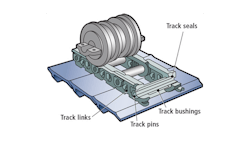
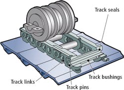
The parts being handled in this application are track links, which when coupled together using pins and bushings form the track-chain assembly used to propel large earth moving equipment such as bulldozers. The manufacturer produces a variety of replacement track links that can weigh anywhere from 8 to 80 pounds each, come in right-handed and left-handed versions, and can be up to 17 inches long.
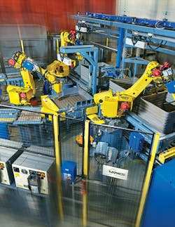
This application feeds track links from bins into a heat treat process. During operation, track links arrive in full or partially-full 64 cubic-foot bins. The conveyor indexes two bins into position such that a single robot from Fanuc Robotics (Rochester Hills, MI, USA;www.fanucameria.com) can pick from either bin.
A single ScanningRuler 3D camera is mounted to a motion system above the two bins. The ScanningRuler 3D camera is essentially a factory-calibrated 3D sensor that combines a 756 x 512 pixel CMOS sensor camera and a built-in, servo-driven, class 2M, 660 nm, red laser scanner that sweeps through the volume of view (VOV) to create a 3D point cloud of the parts in the bin.
Connected to the 3D sensor, a PC running the PLB software analyzes and compares the information contained in the point cloud with the CAD model of the part to determine the next best pick and provide its coordinates (x, y, z, yaw, pitch, roll) to the robot controller, which does all the motion planning.
The robot then picks the part and places it in the desired location to enter the first heat treat process. At the same time, a Tolomatic (Hamel, MN, USA; www.tolomatic.com) slide and servo driven belt drive from Allen Bradley (Milwaukee, WI, USA; http://ab.rockwellautomation.com) index the 3D sensor to the other bin for scanning. By alternating between two bins, MWES engineers were able to minimize the impact of the 4 to 4.5 second 3D sensor scan time, and meet the customer's average 14 second per pick cycle time requirement.
If the PLB system is unable to determine a best pick scenario, the robot is programmed to shuffle parts around in the bin with its magnetic gripper assembly from Magswitch Technology (Lafayette, CO, USA; www.magswitch.com.au/) before the next 3D image is acquired.
"Ideally, all the track links in a given bin would be identical, however there's always a chance that bins contain mixed parts," Wood explains. "Because this system matches the 3D point cloud with CAD files of the parts, the robot will pick around any track links that are not the right size or of the correct right-hand or left-hand version."
For more information about the PLB robot guidance system from SICK email:[email protected].


