Robots and vision team up to speed automation tasks
Automation tasks are benefiting from the numerous types of camera systems and image sensors that are now available.
In the past, robots were limited to perform repetitive tasks on similar parts that were fixed within known coordinates. Because of this, they were limited to high-volume applications where, once programmed, such tasks could be performed rapidly, reducing manufacturing costs. Today, by adding vision-based systems, integrators can offer more flexible systems that can address a wider range of applications that require smaller production volumes.
To accomplish these tasks, developers can choose from a number of different configurations of vision systems, each of which remain highly application-dependent. When choosing a vision system for a particular system, many different types of technologies are available that employ single, dual or multiple cameras, structured or pattern projection systems and Time of Flight sensors (see "Choosing a 3D vision system for automated robotics applications"Vision Systems Design, December 2014; http://bit.ly/1BUQaFw).
As well as considering the different types of image sensors that are available, developers must take account of the types of lighting required to best illuminate the part that is either to be inspected or picked. Depending on the part, lighting configurations such as on or off-axis LED illumination, dome lighting, rear illumination or structured illumination may be required. Once images are captured, they can be processed in a variety of ways using a number of different software packages ranging from simple vision toolkits, to advanced OEM toolkits to proprietary packages.
Single camera systems
To perform many pick and place tasks only requires the use of single camera systems. In the simplest configurations, a camera is placed in a fixed position above the object to be inspected and the object analyzed by off-the-shelf and/or custom software. A robot positioned next to the vision system then performs the task of picking the part and placing it into the appropriate bin.
Many examples of such systems were on show at this year's VISION Show in Stuttgart, Germany. At Festo (Esslingen, Germany;www.festo.com), for example, Gerhard Hölsch, Product Manager Machine Vision, explained how the company's Parallel Kinematic Robot system EXPT is being used by a large cookie manufacturer to place different types of cookies into plastic containers. After the different types exit from multiple ovens and merge onto a single conveyor, the cookies are imaged by a smart camera enclosed in a custom housing above the conveyor.
A homogeneous white dome light illuminates the cookies. Intelligent Software tools in the camera then determine the quality and shape of the cookie as well as its position on the conveyor. The results of this image processing are then transferred over the camera's Ethernet interface to Festo's robot controller with tracking functionality.
Here, the coordinates of each cookie are then used to instruct the robot to pick the cookies from the conveyor and place them into the appropriate location in the plastic containers. According to Hölsch, a number of these systems are currently being used by the manufacturer to pack hundreds of thousands of cartons per year.
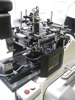
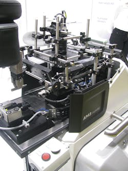
Such single camera systems were also being demonstrated by Bosch (Stuttgart, Germany;www.bosch-apas.com) as part of its automated production assistant (APAS) to inspect precision cylindrical metal parts (Figure 1). To accomplish this task effectively, Bosch uses shape-from-shading to highlight the defects present on the highly specular surfaces of the objects.
In this method, the gradient and curvature of features within an image can be realized by capturing multiple features of an object by illuminating it in an uneven way to obtain a topographic map (see "Lighting system produces shape from shading,"Vision Systems Design, January 2008; http://bit.ly/2g2QXMd).
Instead of using a commercially built system, such as that from SAC Sirius Advanced Cybernetics (Karlsruhe, Germany;www.sac-vision.de), Bosch chose to light the part with four white LED panels from Vision and Control (Suhl, Germany; www.vision-control.com) placed around the part at roughtly 45o angles.
To obtain a 360° map of the surface of the cylindrical part, the part is first positioned by a Fanuc industrial robot in a fixture that is then moved into the field of view of a UI-3370CP CMOS camera from IDS Imaging Development Systems (Obersulm, Germany; https://en.ids-imaging.com) equipped with a 25mm Fujinon lens from Fujifilm (Tokyo, Japan;www.fujifilm.com).
As parts are rotated in the fixture, images are captured as each of the LED lights is switched sequentially and the images transferred over a USB3 interface to the system's host PC. Here, Bosch's proprietary shape-from-shading algorithm in conjunction with image analysis software from MVTec Software (Munich, Germany;www.mvtec.com) are used to analyze the parts at a rate of approximately two parts per second.
Apart from the use of shape-from-shading, one of the most novel features of the system is the force limited nature of the robot. While many robot vendors employing torque sensors and/or cameras on the robot (see "Robots increase manufacturing productivity,"Vision Systems Design, April 2016, http://bit.ly/1Dc4QO1) to allow them to be used in un-caged environments, Bosch has taken a different approach. Rather, the company has developed a padded skin employing two sets of 120 capacitive sensors placed around the robot, making the system fault tolerant. When approaching an object, the robot will then stop approximately 3in from a human operator without requiring any force to be applied to the robot or robotic arm and thus eliminating the needed for any torque sensors.
Stereo vision
One of the most common methods of determining the position of an object in the field of view of a camera is to use stereo vision. In this method, depth is computed by obtaining two images from two different perspectives, and extracting 3D information by examining the relative positions of objects in the two images and solving what is known as the correspondence problem.
For applications that require vision-based robotic systems to accurately determine the position of objects, using stereo vision methods, systems integrators must fully understand the nature of their application. This involves understanding the types of cameras used in the system, their resolution, the focal length of lenses that are used and the minimum distance the camera system is placed from the object. Knowing this, the baseline distance between the cameras can be computed and the error at specific z (depth) values can be computed.
Such mathematical computations have been made easier by companies such as Nerian Vision Technologies (Leinfelden-Echterdingen, Germany; https://nerian.com) that has developed an easy to use online calculator to perform this task. Available athttp://bit.ly/2fZNY9O, the calculator allows parameters such as image sensor properties, focal length of lenses and minimum camera distances to be entered and computes the stereo baseline distance required by the stereo cameras. At the same time, the depth error at a variety of image depths is computed. By using this tool, systems developers can properly configure stereo vision systems to meet their specific application.
Many OEMs such as FLIR Integrated Imaging Solutions (Formerly Point Grey; Richmond, BC, Canada;www.ptgrey.com) and IDS offer integrated, pre-calibrated stereo cameras. Although these save the systems developer the time of precisely mounting, configuring and calibrating dual camera systems, they are somewhat limited in the applications which they can be used since the cameras cannot be moved further apart to increase disparity accuracy.
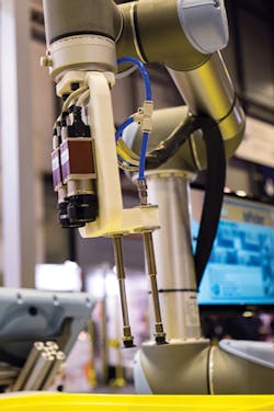
For this reason, many systems developers choose to configure stereo camera systems to meet the needs of specific applications. One of these, Infaimon (Barcelona, Spain;www.infaimon.com) demonstrated such a stereo vision system at this year's VISION show (Figure 2). As a demonstration designed to highlight bin-picking, the system uses two Mako G-125 PoE GigE cameras from Allied Vision (Stadtroda, Germany; www.alliedvision.com) mounted on a UR-5 robot from Universal Robots (Odense S, Denmark; www.universal-robots.com).
"While many bin-picking systems use structured lighting or pattern projection to create a 3D point cloud of the object, such approaches may not be suitable for objects with specular shiny surfaces," says Isaac Miko of Infaimon. Instead, stereo camera systems can be used. As the robot moves in a pre-defined trajectory within the 3D space, multiple images are taken creating a 3D model of the environment.
Features within the parts such as holes are then determined using blob analysis. With the 3D model, the best candidate for picking is computed taking into account whether or not the robot will collide or be trapped with other parts or the bin. Positional coordinates and orientation are then computed on an industrial PC and used by the robot controller to pick the part from the bin.
3D imaging
While stereo vision systems can be used effectively for certain types of applications, they are unsuitable in systems that require the 3D models of the part to be created. In such systems, structured lighting, pattern projection systems or Time of Flight sensors can be used.
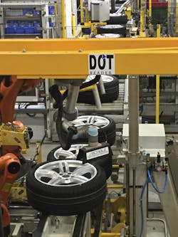
Tasked with analyzing the Department of Transport (DOT) codes on tires for a large German automobile manufacturer, for example, Peter Scholz Software + Engineering GmbH (Weiden in der Oberpfalz, Germany;www.scholzsue.de) developed a vision-based robotic system to perform the task (Figure 3).
Reading the DOT codes placed around the rim of the tire cannot be accomplished with traditional stereo techniques because the DOT codes are composed of black lettering on black rubber. Thus, rather than use stereo cameras, a LJ-V 7060 3D inline profilometer from Keyence (Elmwood Park, NJ, USA;www.keyence.com) was mounted on a UR-5 robot from Universal Robots.
As the tires progress along the production line, information such as the expected tire size code, tire plant code, tire brand and the week and year the tire was made are read by a PC from the manufacturer's PLC. To check whether this information is consistent with the information on the tire, the laser scanner is rotated over 440o around the tire by the robot.
Profile data of the tire is then sent from the scanner to the host PC where a 3D point cloud model of the surface of the tire is computed. Because the DOT codes are raised above the surface of the tire, the 3D point cloud is then sectioned and transformed into a 2D image. From this image, the DOT codes are read and compared with the information from the manufacturer's database. For new DOMs (Date of Manufacturing) changing every week, two independent manual input stations allow operators to enter new DOMs inline into the database. Inputs must be identical in both stations. If incorrect, a robot, positioned further down the production line removes the tire for re-processing.
Adding flexibility
Choosing which type of 3D vision system is highly application-dependent. While laser range finders using Time of Flight (TOF) methods can be used to locate distant objects, stereo imaging systems may be better suited to imaging high-contrast objects. However, to image parts such as DOT codes on tires may require more flexible systems that employ structured-light systems mounted to robots. By mounting such image sensors to robots, systems integrators are able to reduce the cost of visualizing large parts with single-camera systems.
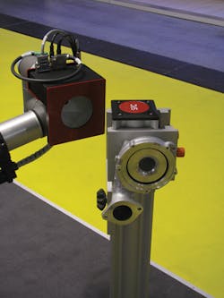
Indeed, at last year's VISION show, a number of companies, including SAC Sirius Advanced Cybernetics showed how, by mounting the company's Trevista camera on a UR-5 robot from Universal Robots, the shape-from-shading-based camera could be used to image parts from multiple views (Figure 4).
Perhaps more impressive, however, was a demonstration developed by David Dechow, Staff Engineer at Fanuc Robotics (Rochester Hills, MI;www.fanucameria.com) that showed how different surfaces of an object can be illuminated differently using a single camera and lighting system with a smart controller (see "Smart controllers add lighting flexibility to robotic systems," page 28, this issue).
Smart controllers add lighting flexibility to robotic systems
For large complex parts such as engine blocks, adding cameras to robotic systems provides the flexibility to view objects at numerous angles. As well as reducing the amount of cameras required to obtain multiple views, such systems do not require the part to be fixtured and can be easily reconfigured for a variety of objects of different sizes and shapes.
As with every vision system, lighting plays a key role in ensuring that captured images are obtained with maximum contrast. In many cases, however, different surfaces of the object may require unique and specific types of illumination. In such cases, it may be necessary to change dynamically both the intensity of the light and how it is strobed.
As David Dechow, Staff Engineer at Fanuc Robotics (Rochester Hills, MI, USA;www.fanucameria.com) explains, this task can be made simpler by employing the latest generation of smart lighting controllers.
In a demonstration shown at last year's Automate show in Chicago, Dechow showed a robotic-based vision system capable of illuminating a variety of different parts with different lighting parameters. In configuring the system, a custom camera from Kowa (Aichi, Japan;www.www.kowa.co.jp) built especially for Fanuc was positioned onto a Fanuc LR MATE industrial robot.
To illuminate the part, a 120mm ring light from CCS America (Burlington, MA, USA;www.ccsamerica.com) was mounted onto the camera. To accommodate the different surfaces of the objects being imaged, it was necessary to control both the intensity and the pulse duration of the lighting as it moved across each objects field of view.
To accomplish this, Dechow interfaced an LED lighting controller from Gardasoft Vision (Cambridge, UK;www.gardasoft.com) between the LR MATE industrial robot and the 120mm ring light. To program the robot, Dechow programmed the robot controller to move the robot in several different paths around the various parts to be imaged.
As the robot reaches a specific point in the path, the program triggers the camera to start the exposure. Simultaneously, the trigger is sent to the Gardasoft controller to pulse the ring light for a specific time and current (brightness) level. After the image is captured, the lighting controller is then updated by the program running on the robot controller as to the next pulse duration and brightness required at the next position of the robot.
As the camera is triggered at the next position, the lighting is then automatically configured for different pulse durations and brightness levels. In this way, a single program running on the robot controller can dynamically alter the lighting of multiple objects as they are imaged by the camera. A video of the system in operation can be found athttp://bit.ly/2fnNnv6.
Companies mentioned
Allied Vision
Stadtroda, Germany
www.alliedvision.com
Bosch
Stuttgart, Germany
www.bosch-apas.com
Fanuc Robotics
Rochester Hills, MI, USA
www.fanucameria.com
Festo
Esslingen, Germany
www.festo.com
Fujifilm
Tokyo, Japan
www.fujifilm.com
Gardasoft Vision
Cambridge, UK
www.gardasoft.com
IDS
Obersulm, Germany
www.ids-imaging.com
Infaimon
Barcelona, Spain
www.infaimon.com
Kowa
Aichi, Japan
www.kowa.co.jp
MVTec Software
Munich, Germany
www.mvtec.com
Nerian Vision Technologies
Leinfelden-Echterdingen, Germany
https://nerian.com
Peter Scholz Software + Engineering GmbH
Weiden in der Oberpfalz, Germany
www.scholzsue.de
FLIR Integrated Imaging Solutions
Richmond, BC, Canada
www.ptgrey.com
SAC Sirius Advanced Cybernetics
Karlsruhe, Germany
www.sac-vision.de
Universal Robots
Odense S, Denmark
www.universal-robots.com
Vision and Control
Suhl, Germany
www.vision-control.com
For more information about robotics companies and machine vision products, visitVision Systems Design's Buyer's Guide buyersguide.vision-systems.com
