Camera Link primer
The Camera Link specification provides maximum functionality, while allowing individual manufacturers to offer unique product features.
The Camera Link standard defines a complete interface between digital cameras and frame grabbers. This interface includes a high-bandwidth path for transferring data, bidirectional serial communications, and timing information to the frame grabber to acquire the image. It also includes control lines for real-time triggering and synchronization of the camera. The Camera Link interface uses a 3M Corp. (Austin, TX) MDR 26 connector. A standard cable is defined for use with all Camera Link equipment.
Camera Link provides three levels of implementation: Base, Medium, and Full. The Base configuration is the most commonly used and defines a single connector and cable between the camera and the frame grabber. It specifies data transfer rates up to 1.5 Gbits/s (198 Mbytes/s), which are sufficient to interface cameras delivering up to 66 MHz at a maximum 24-bit output. These parameters cover the majority of cameras available today.
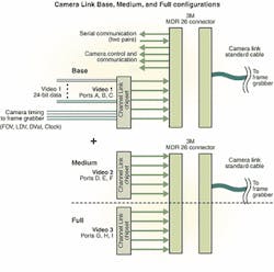
The Base configuration contains all the elements for real-time acquisition and control (see figure). At the core of this configuration is a National Semiconductor (Santa Clara, CA) Channel Link chipset. Channel Link provides lossless hardware compression in a single-chip platform. Up to 28 bits of TTL-level data and timing are compressed into five differential pairs, which consist of a clock pair and four data pairs. The differential RS-644 output provides high noise immunity and signal integrity over a distance of up to 10 meters.
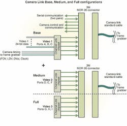
The Base configuration contains all the elements for real-time acquisition and control (top). The Channel Link chipset provides lossless hardware compression in a single-chip platform. Camera Link uses the 28 bits in the Channel Link chipset to transfer 24 bits of data and four camera-timing signals. The timing signals are Frame Data Valid (FDV), Line Data Valid (LDV), Data Valid (DVal), and Clock. The Camera Link Medium and Full configurations provide additional video channels on a second Camera Link port (bottom). The Medium configuration adds another 24-bit, 66-MHz data path and 4 bits of camera timing via a second Channel Link integrated circuit (Video 2). The Full configuration provides a third video channel (Video 3) and can support up to 72 bits at 66 MHz and transfer up to 4.7 Gbits/s (594 Mbytes/s). Both configurations use a second MDR 26 connector and Camera Link cable and are intended to work in conjunction with the Base configuration.
The Camera Link specification uses the 28 bits in the Channel Link chipset to transfer 24 bits of data and four camera-timing signals. These four timing signals are Frame Data Valid (FDV), Line Data Valid (LDV), Data Valid (DVAL), and Reserved Spare. The FDV and LDV signals mark the start of a frame or a horizontal line.
The Channel Link chipset has a 20-MHz minimum clock requirement. For cameras with data clocks slower than 20 MHz, the data are clocked at a higher rate and padded with null data. The Data Valid flag distinguishes valid data from null bits. The Spare line can be assigned to functions such as strobe trigger output or other signaling as deemed necessary in the future. The 28-bit video and timing data are encoded by the transmitter, then transferred across five differential pairs, and lastly reconstructed into its original format by the Channel Link receiver.
The Base configuration includes a bidirectional serial communications port. The communications are of a RS-232 style but are driven at RS-644 levels to match the other signaling on the interface. Because the communications port is part of the Camera Link interface on the frame grabber, frame-grabber manufacturers must provide user access.
Manufacturers provide two methods of access. Some frame-grabber manufacturers provide a cable to connect the PC's standard RS-232 port into the frame grabber. The RS-232 communications to the camera are converted directly to RS-644 levels and then passed down the cable to the camera. Camera-control software can address the PC's RS-232 port and communicate with the camera. This setup is the simplest approach, but it requires an additional cable at the PC.
Some manufacturers find the additional cable undesirable and costly. Instead, they might provide a dynamic-link-library (DLL) file for accessing the communications port. The Camera Link specification defines four commands for communicating with the camera through a DLL file. These commands allow users to open, close, read, and write to the serial port. The DLL file links the communication string to the hardware commands necessary to shuttle it through the serial port. This approach doesn't affect the command syntax. Camera manufacturers and other designers simply read and write the same control commands, but address the DLL file rather than a RS-232 port. This approach is clean and eliminates the second cable, but requires that software designers allow provisions to direct commands to either a DLL file or a RS-232 port.
Camera controlFour camera control lines complete the Base configuration of Camera Link. Designated CC1 to CC4, these lines are used for real-time control and triggering of the camera. The Camera Link specification is designed to provide maximum functionality, while still allowing individual manufacturers to have unique product features. To this end, the specific functions of these lines are not specified.Frame-grabber manufacturers support these lines with programmable high-speed ports and are prepared to offer signaling that is defined by the camera manufacturers. Camera manufacturers can then freely link these lines to control any camera functions they want to offer. Examples of features that these lines support are asynchronous reset (Vinit), horizontal drive (Hd), vertical drive (Vd), integration control, and pulse-width exposure control. Because these lines are directly driven, real-time control of the camera features is possible with negligible delays. The power and flexibility of these control lines allow Camera Link manufacturers to provide varieties of product features best suited to their target end users.
Medium and FullThe Camera Link specification also defines Medium and Full configurations. These two configurations add more functionality by providing additional video channels on a second Camera Link port. The Medium configuration adds another 24-bit, 66-MHz data path and 4 bits of camera timing via a second Channel Link integrated circuit (Video 2). The Full configuration provides a third video channel (Video 3) and can support up to 72 bits at 66 MHz. A Full configuration can transfer an impressive 4.7 Gbits/s (594 Mbytes/s).The Medium and Full configurations use a second MDR 26 connector and Camera Link cable. Although the pinout differs slightly on the second connector from the first connector, the standard Camera Link cable is designed to work with both pinouts. The Medium and Full configurations are intended to work in conjunction with the Base configuration. All camera controls, communications, and timing signals are handled through the Base port. The Medium and Full configurations simply add additional video capacity to the Base configuration.
The Base configuration operates satisfactorily for most cameras. The Medium and Full configurations will come into play when data rates exceed 1.5 Gbits/s (198 Mbytes/s) or the data path is more than 24 bits. Though a Medium or Full configuration requires two cables, the cables are now standard, smaller, less costly, and less bulky assemblies that might otherwise contain as many as 150 conductors.
Data port assignmentsTo ease connectivity between devices, the Camera Link specification standardizes the format of the data to be transferred through the interface. Each of the 24-bit video channels is divided into three 8-bit ports and is assigned to pins on the Channel Link chipset. Video 1 on the Base connector contains Ports A, B, and C. Labeling continues incrementally through Port I on Video 3. Standard port assignments are designated for each type of data to be transferred. For example, single-tap, 8-bit data uses Port A. Single-tap, 10-bit data uses Port A and the two least significant bits of Port B. Color 24-bit data uses Ports A, B, and C, where Port A is the red byte, Port B is the green byte, and Port C is the blue byte. (For complete definitions, see Appendix C in the Camera Link specification.)Assignments of the data ports are an important feature of the Camera Link specification. By knowing the format of the data stream, frame-grabber manufacturers can easily configure a system to acquire the data.
Steve Kinney is product marketing manager at Pulnix America Inc., Sunnyvale, CA 94089.

