Camera Link smoothes systems integration
Camera Link interfacing standard still needs more work to make products truly compatible.
By Andrew Wilson, Editor
Because of the disparate nature of camera outputs, camera-to-frame-grabber interfaces were, in the past, custom-built using bulky cabling. To effectively develop machine-vision systems today, systems integrators need to accurately specify the cameras, frame grabbers, and cables needed to meet their design goals. To improve cabling needs and ease systems-integration tasks, many camera vendors are embracing the proposed Camera Link interface standard (see "Camera Link Specifications," Automated Imaging Association; www.machinevisiononline.org).
Despite the swell of industry acceptance, the outputs of many linescan, time-delay-and-integration (TDI), and area-array cameras are still nonstandard, which makes the interfacing of digital cameras to frame grabbers difficult (see Vision Systems Design, November 2001, p. 34). And, for use in harsh environments, some cameras might also have to be connected to nonstandard fiberoptic interfaces. Fortunately, many designers have adopted Camera Link-to-fiber and fiber-to-Camera Link converters to perform this task (see Vision Systems Design, December 2001, p. 38).
Mark Butler, product manager at Dalsa (Waterloo, Ont., Canada), says, "The Camera Link interface standard is an informal agreement among member companies to comply with the connector choice and pinouts. The agreement is not binding on member companies, and there are no formal mechanisms in place to verify that a product is conforming to the standard. To address this issue and add more value to the Camera Link standard, the Camera Link committee is examining a self-verification process." In its present form, the standard is merely designed to reduce the cable and development costs for system integrators by providing a common connection.
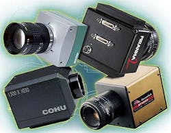
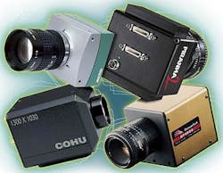
Mikrotron's MC1301 1280 X 1024-pixel CMOS camera runs up to 100 frames/s and uses a 16 bit Base-configured Camera Link interface to support digital frame grabbers. Dalsa's Piranha2 camera offers multiple methods for exposure control, including the use of the serial communications port of the Camera Link interface. Cohu's Camera Link-compatible camera, the 7500 Series, has been developed as a megapixel imager for medical-imaging, inspection, and test applications. The 1300 X 1030-pixel Camera Link-compatible camera can output 10-bit images at up to 24 frames/s over a Base-configured Camera Link interface. DuncanTech uses the Medium configuration of the Camera Link standard to transfer 1600 X 1200-pixel color data from its DT4000 single-CCD camera at frame rates up to 10 frames/s. In operation, the camera can be configured to offer 8 bits/pixels using four taps or 10 bits using three taps, depending on the dynamic range required.
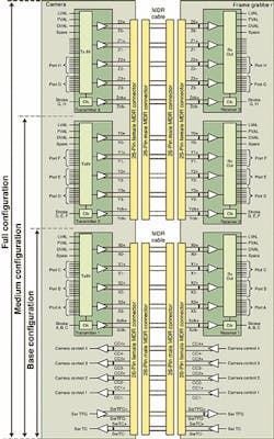
Transmitters and receiversTo accommodate a number of linear and area-array cameras at different rates, the Camera Link standard is offered in three configurations: Base, Medium, and Full (see Fig. 1). Whereas the Base configuration uses one Channel Link transmitter/receiver pair to transmit up to 24 bits (maximum) of data from the camera to the frame grabber, two Channel Link transmitter/receiver pairs are used in the Medium configuration to transmit up to 48 bits of data. In the Full configuration, three transmitter/receiver pairs allow a maximum of eight taps of 8 bits/pixel or 64 bits of image data to be transmitted.The type of Camera Link connection that is used by specific camera vendors is largely determined by the number of taps (or output stages) of the CCD or CMOS imaging sensor in the camera. Single-tap linear and area-array cameras, for example, that deliver 8 bits/pixel only require the Camera Link Base configuration. Indeed, single-tap cameras of this type could theoretically support 24 bits/pixel of image data using Ports A, B, and C of the Base configuration.
An example of a single-output, digital linescan camera is the LD3500 from PerkinElmer Optoelectronics (Santa Clara, CA). Originally built by Reticon, this camera is offered with a 512, 1024, or 2048 X 1 photodiode array and clock speeds up to 40 MHz. As the video output from this camera is output as 8-bit video data, a single Camera Link Base connector can be used to transfer data from the camera to the frame grabber.
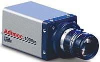
For area-array cameras, vendors are also looking to migrate from the established RS-644 interface to Camera Link. For example, in the design of its 1000-m, 1004 X 1004-pixel area-array camera, Adimec (Gold Canyon, AZ) selected a 2/3-in. format CCD sensor that can output up to 50 progressive images/s via one or two taps on the sensor at 8 or 10 bits/pixel (see Fig. 2). To accomplish the 10-bit/pixel rate over the Camera Link interface, the camera must use ports A, B, and C in the Base configuration.
More taps, more speedAs systems integrators demand faster speed from their machine-vision systems, linescan and area-array camera vendors are responding with multitap designs. One such linescan camera is the Pirahna2 P2-4x from Dalsa. With selectable four 8- or 10-bit outputs at 40 MHz, the camera can deliver a maximum throughput of 160 MHz. It is available in linescan implementations from 4k X 1 to 8k X 1 pixels.Butler says, "Any four-tap camera that provides at least 8 bits of information per channel fits the Medium configuration as outlined in the Camera Link standard, whether the systems integrator chooses to output 8, 10, or 12 bits/pixel. A good way to determine Base and Medium configurations is to realize that each increase in configuration adds 24 more bits of data. The Base configuration can handle 2 X 12-bit and up to 3 X 8-bit cameras. The Medium configuration can handle up to 4 X 12-bit, 4 X 8-bit, and up to 6 X 8-bit cameras. Therefore, for the two-tap version of the Piranha2 camera (the P2-2x), only the Base configuration is required."
DuncanTech (Auburn, CA) also is using the Medium configuration Camera Link standard to transfer 1600 X 1200-pixel color data from its DT4000 single-CCD camera at rates of up to 10 frames/s (see photo at the top of this article). The camera can be configured to offer 8 bits/pixel using four taps or 10 bits/pixel using three taps, depending on the dynamic range required by the systems integrator.
Camera controlIn the Camera Link specification, four low-voltage-differential-signal (LVDS) pairs are reserved for general camera control lines. Companies, such as Dalsa, are using these signal pairs for external sync, pixel reset, and direction control for bidirectional TDI cameras. Other companies, such as PerkinElmer, are using them for line transfer, line reset, and future use. Although these differences could be confusing to system integrators, the Camera Link specification only states that four LVDSs are reserved."Frame-grabber and camera companies wanted it this way to allow greater flexibility and to provide a future path forward for unforeseen input requirements," says Dalsa's Butler. "Prior to the initial Camera Link meetings, frame-grabber companies had developed reconfigurable I/Os to handle the myriad of camera inputs and outputs from different vendors. It was undesired to constrain the Camera Link standard because frame grabbers could handle a more open standard, and this openness or flexibility offered by the standard was seen as a benefit," he explains. "Even though the standard is open, similarities between camera-control signals with respect to function can be found among camera vendors. However, they may not be similar enough in detail, for example, to use the same pulse edges (rising or falling) to trigger the camera. Moreover, significant differences can be found between area- and linescan camera-control signals," adds Butler.
Steve Weir, a senior OEM sales engineer with Cohu (San Diego, CA), sees the same problem. Currently, the company offers only one Camera Link-compatible camera—the 7500 Series (see photo at the top of this article). Developed as a megapixel imager for medical-imaging, inspection, and test applications, this 1300 X 1030-pixel camera can output 10-bit images at up to 24 frames/s over a Base configuration.
"Of the four LVDSs reserved for general camera control," says Weir, "CC1, CC2, and CC3 are used for vertical sync, horizontal sync, and asynchronous reset." This, of course, places the burden of interfacing on the camera or frame-grabber vendor. And, as Weir admits, since there are no formal requirements in place to verify whether a camera complies with the standard, each new frame grabber must be tested for compatibility.
Serial communicationsTo control functions such as camera shuttering, snapshot, and integration modes, the Camera Link standard specifies serial-to-frame grabber (SerTFG) and serial-to-camera (SerTC) signals for communication to and from the frame grabber. "The serial communication channel is an important feature of the Camera Link standard," says Ingo Lewerendt, product manager with Basler (Exton, PA)."Because each customer has different requirements, the camera must be configurable on-line during the imaging process," he says. Basler cameras use the serial communication channel to make these on-the-fly changes. In addition, Basler's Camera Configuration Tool software allows systems integrators to modify camera settings. "All Basler cameras also feature a level-controlled mode that allows customers to define the trigger speed and the exposure time with only one signal (CC1)," adds Lewerendt.
Dalsa also uses the SerTFG and SerTC signals in its Piranha2 line (see photo at the top of this article). Butler says, "With Piranha2, there are multiple methods for exposure control. A dedicated camera control signal (CC2) can be used. Or systems integrators can program the exposure time through the serial communications port. Lastly, the camera control signal for Exsync (CC1) can be used where the falling pulse edge triggers the camera and the long duration time of the pulse signal defines the integration time. Serial communications enable the possibility of autoconfiguration between a frame grabber and a camera. Although not part of the Camera Link standard, the committee is discussing the role of autoconfiguration," adds Butler.
Mikrotron (Eching, Germany) manufactures the MC1301 1280 X 1024-pixel CMOS camera that runs up to 100 frames/s using a 16-bit Base configuration Camera Link interface to support digital frame grabbers (see photo at the top of this article). "Because of the configuration possibilities of the MC1301 camera, such as camera clock selection, dual row binning, and our patented Imageblitz shutter release, software must be defined by the systems integrator," says Bernhard Mindermann, general manager of Mikrotron. "Our camera is supplied with the Inspecta-4C Camera Link frame grabber, an application programming interface, and a camera configuration tool, where all parameters for the camera and frame grabber can be set from an editable .cam file." Such control is currently proprietary to Mikrotron cameras and frame grabbers.
Future developmentsFuture area- and linear-array cameras are expected to be larger and faster. Accordingly, the camera data rate might exceed the data-transfer rate of the PCI bus for a single frame-grabber node. To circumvent this issue, Dalsa's Piranha2, for example, offers an extra programmable mode of operation when providing data to the frame grabber. This mode allows two frame grabbers connected in the Camera Link Base configuration to be used with a single camera. In operation, data from taps 1 and 2 are sent from the first connector in the Base configuration, and data from taps 3 and 4 are sent from the second connector also in the Base configuration. As a result, the frame-grabber vendor requires two Base-configured frame grabbers and a dual PCI-bus computer to handle the data.As these larger linear and area-array cameras become commonplace, vendors will seek to build on the Camera Link interface. "The upper speed limit is not a question of the frame grabber," says Basler's Lewerendt. "The upper limit of the pixel clock signal that can be handled by the chipsets used with Camera Link is about 85 MHz, but the data signal across the cable can be up to 3.5 times faster," he adds. At these higher speeds, the cable becomes very sensitive and has difficulty protecting the signal against disturbances. If you need to increase the speed, there is no way to do so other than by opening parallel data paths. "Currently, Basler is working with the Camera Link committee to extend the Full configuration to include a 10-tap solution," says Lewerendt.
While the Camera Link interface has reduced the cabling requirements used between digital cameras and frame grabbers in the machine-vision and image-processing industry, much work still needs to be accomplished by the Camera Link committee. This work includes the solidification of camera-control-signal standards and the development of a Full autoconfiguration protocol. Until then, the task of interfacing cameras to frame grabbers will still be a burden for camera manufacturers, frame-grabber vendors, and systems integrators alike.
Company InformationDue to space limitations, this Product Focus does not include all of the manufacturers of the described product category. For information on other suppliers of CCD cameras, see the 2002 Vision Systems Design Buyers Guide (Vision Systems Design, Feb. 2002, p. 62).AdimecGold Canyon, AZ 85218Web: www.adimec.comAtmel-GrenobleTotowa, NJ 07511Web: www.atmel-grenoble.comBaslerExton, PA 19341Web: www.baslerweb.comCohuSan Diego, CA 92186Web: www.cohu-cameras.comDalsaWaterloo, Ont., Canada N2V 2E9Web: www.dalsa.comDuncanTechAuburn, CA 95603Web: www.duncantech.comMikrotronD-85386 Eching, GermanyWeb: www.mikrotron.dePerkinElmer OptoelectronicsFremont, CA 94538Web: www.opto.perkinelmer.com


