February 2015 Snapshots: 3D vision, space imaging, vision-guided robots, Google self-driving car
Vision-guided underwater turtle robot is self-charging
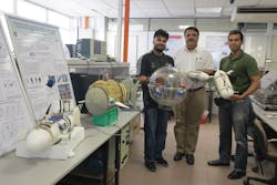
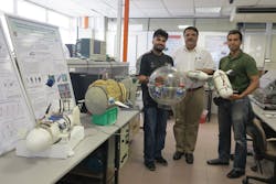
Researchers from the National University of Singapore (NUS; Singapore; www.nus.edu.sg) are developing an underwater robotic turtle that can autonomously navigate while also self-charging, allowing it to stay underwater for long periods. Led by S.K. Panda, associate professor at NUS, the robotic sea turtle can move about underwater and dive to deep depths vertically, using front and hind limb gait movements.
"Our turtle robot does not use a ballast system which is commonly used in underwater robots for diving or sinking functions," explained Panda. "Without this ballast system, it is much smaller and lighter, enabling it to carry bigger payloads so that it can perform more complicated tasks such as surveillance and water quality monitoring."
The NUS turtle self-charges using solar panels when the robot surfaces. A vision system also allows the robot to track and follow given targets underwater. The system consists of an on-board bottom-facing camera module that performs pan, tilt and zoom and auto focus from 0.1m to ≥ 10m. In addition, the camera features automatic image adjustment with manual override and can achieve a frame rate of 30 fps.
Google introduces operational self-driving car
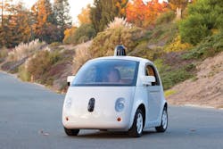
After unveiling what was essentially a mockup of its first self-driving car in May, Google (Menlo Park, CA, USA; www.google.com) has announced that its first fully-functioning self-driving vehicle has been produced and will be introduced in California this year.
Google is touting the vehicle as its first complete prototype for fully autonomous driving. The car's vision system features a number of different components including a LIDAR laser system from Velodyne (Menlo Park, CA, USA; www.velodynelidar.com). The device can also rotate 360° and take up to 1.3 million readings per second at distances up to 100m. Cameras mounted on the exterior of the vehicle provide stereo vision. This allows the system to track an object's distance within a 50° field of view to a distance of 30m.
In addition to the LIDAR and stereo vision technologies, the car also uses radar to adjust the throttle and brakes continuously, essentially acting as adaptive cruise control while taking into account the movement of cars around the vehicle. Software from Google integrates the data from the vision system at a rate up to 1 GB/s to build a map of the car's position on the road. Eventually, Google will develop 100 prototype cars that operate with only two controls: go and stop.
Vision sensors inspect medicine in automated verification process
Counterfeit medicine products with ineffective or incorrectly-dosed active ingredients can cause considerable harm to patients. As a result, a European Union directive stipulates that all prescription medicine must have a unique identifier on its packaging by 2017. In an effort to remove these counterfeit products from the market, a vision-based identification system called "securPharm" was developed.
The system was tested in a pilot program in May of 2013 and will be formally introduced in 2017. Each medicine product is given a unique identifier during production that includes an individual product code, serial number, batch number, and expiration date. Locating this identifier throughout production is the only way to guarantee proper checks along the supply chain, which includes manufacturing, wholesaling, and the pharmacy.
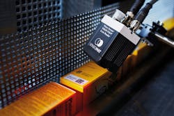
To automate the verification process, a standardized, machine-readable code must be printed on the packaging. In addition to text, the identifier also includes a 2D data matrix code which if not properly read will result in the withdrawal of a product from the supply chain. To locate the identifier, a code reader such as a smart camera or vision sensor like the Vision code reader VISOR V20 from SensoPart (Gottenheim, Germany; www.sensopart.com) must be utilized.
These VISOR V20 code readers feature integrated object detection that read 1D, 2D data matrix and optical character recognition codes. The code readers feature a 1/1.8in monochrome 1280 x 1028 CMOS image sensor, a 12 mm integrated lens, and white, red, IR, and UV LEDs. In addition to locating the identifier, the V20 readers can detect small defects in the print image and export quality parameters. All elements are recorded and analyzed in a reading process. V20 readers can read up to 50 codes per second, depending on the application.
3D vision-guided robot cuts chicken fillets
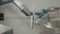
Cutting chicken fillets from a carcass is a repetitive and tedious task that engineers at SINTEF (Trondheim, Norway; www.sintef.no/home) have automated using a robotic 3D vision system called the Gribbot. The system features a robot arm from Denso Robotics (Long Beach, CA, USA; www.densorobotics.com), a Kinect 2 camera from Microsoft (Redmond, WA, USA; www.microsoft.com) and a compliant gripper. The Kinect 2 features an infrared 1080p wide-angle time of flight sensor that achieves a frame rate of 30 fps and a monochrome CMOS sensor that captures video data.
Programming the robotic vision system was performed using LabVIEW from National Instruments (NI; Austin, TX, USA; www.ni.com) and Denso's robotics software.
In operation, a rotating transport system is used to present the carcass to the Kinect camera. The 3D camera scans the carcass and localizes the gripping point-where the gripper should start the scrapping as part of cutting the chicken fillet from the carcass.
"Machine vision makes the entire procedure adaptive as it allows us to localize the gripping point of the fillet independently of the variations in size," says Ekrem Misimi, Research Scientist at SINTEF Trondheim, Norway.
"The Gribbot shows that there is huge potential for the robot-based automation for handling and processing raw material. The aim of our research was to develop a flexible and adaptive robot-based concept that can handle and process raw materials with different material properties and high biological variations," he says.
Body scanner uses 3D vision for clothing measurements
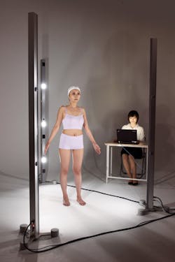
Space Vision's (Tokyo, Japan; http://en.space-vision.jp) portable Cartesia 3D body scanner is a multi-camera vision system that creates a 3D image of a subject within seconds to provide accurate measurements for tailored clothing manufacturers.
"Previously, our 3D scanner was difficult to transport," says Yuji Nishio, Leader of Technical Design Development at Space Vision. As a result, Space Vision has developed a compact system for measuring bodies which can be installed in minutes.
To perform 3D measurement, the Cartesia system projects a laser pattern onto the person being measured, and the reflected light is captured by three board-level UI-1221LE USB 2.0 cameras from IDS Imaging Development Systems (Obersulm, Germany; www.ids-imaging.com) mounted on each of the three separate towers of the scanning system. The cameras feature a 1/3in 0.36 MPixel global shutter CMOS image sensor from ON Semiconductor (Phoenix, AZ, USA; www.onsemi.com) that can achieve a frame rate of 87.2 fps at full resolution. Captured images are then used to create a 3D image of the person in 2s.
Image sensors study comet properties
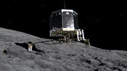
Launched in 2004, the Rosetta space probe has been used to orbit comet 67p and map its nucleus to learn more about the comet's characteristics and physical conditions. In September, a landing site was identified and just months later, the European Space Agency's Rosetta mission landed the Philae lander probe on the comet. Data from the lander's instruments was then transmitted to the Philae Science, Operations and Navigation Centre at France's CNES space agency (Toulouse, France; www.cnes.fr).
Five CCD image sensors from e2v (Chelmsford, UK; www.e2v.com) were used for the imaging devices in Rosetta and Philae. The Rosetta probe features an OSIRIS high-resolution imaging camera, a NAVCAM navigation camera, and a visible and infrared thermal imaging spectrometer (VIRTIS) to study the nature of the solids and the temperature of the surface of the comet. VIRTIS also identifies gases, characterizes the physical conditions of the comet and helped to identify the landing spot for Philae.
The Philae lander was also equipped with a Comet nucleus infrared and visible analyzer (CIVA) which incorporated six identical micro-cameras to take panoramic images of the surface of 67p and a spectrometer to study the composition, texture, and reflectively of samples collected from the surface. Philae also used its Rosetta lander imaging system (ROLIS), a CCD-based camera, to obtain images during the descent of the lander and to take stereo panoramic images of areas sampled by other instruments.
