Vision system helps avoid excavation accidents
Every sixty seconds in the United States, an excavator inadvertently strikes a cable, sewer, water, gas or fiber-optic line. Not only can such accidents cause major damage, they are also expensive to rectify. To avoid such accidents occurring, excavator operators must know the exact position of any buried cables or pipes and the position of the excavator relative to them.
In the past, this has been accomplished by employing grade control systems such as the GCS900 2D Grade Control System from Trimble Navigation (Sunnyvale, CA USA; www.trimble.com).
Such systems employ angle sensors, global positioning systems and a laser catcher mounted on the excavator to measure the relationship between the body, boom, stick and bucket. By doing so, the cutting edge can be determined and the operator directed to the desired depth and slope.
"While useful," says Professor Vineet Kamat of the LIVE Robotics Group at the University of Michigan (Ann Arbor, MI; USA; live.engin.umich.edu), "systems that use global positioning systems can be unreliable since natural or artificial objects can impair satellite reception."
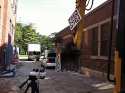
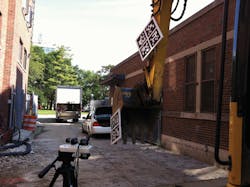
To overcome these limitations, Kamat and his colleagues have developed a machine vision system known as SmartDig that employs off-the-shelf machine vision cameras and pseudo-quick response (QR) codes to perform this task (Figure 1, page 18).
In operation, a large pseudo-QR code is mounted onto the excavator while a reference pseudo-QR code is placed at a known distance.
Two Firefly USB 2.0 cameras from Point Grey (Richmond, BC, Canada; www.ptgrey.com) mounted on a tripod are then used to transfer images of these pseudo-QR codes to a laptop PC.
"Specialized QR codes were developed for this application since standard QR codes are matrix barcodes that are unsuitable for localization," explains Dr. Suyang Dong, Post-Doctoral Scholar at the LIVE Robotics Group, "Since they have been developed specifically as high-density barcodes, they are unsuitable for use in applications where machine vision software must be used to locate their x, y, z, roll, pitch and yaw."
Although the pseudo-QR code appears similar to standard QR codes, the code consists of four quadrants with distinct edges. To localize the position of the pseudo-QR code in 3D space the pixel location of each of the corners in all four quadrants must be determined. To do so, a Gaussian filter is first applied to the captured image to eliminate any high-frequency noise. The gradient and direction of each pixel in the image is then computed and pixels with similar gradients and direction clustered to determine the 16 point edge locations of the four quadrants. Similarly, the edge locations of the reference target image are then computed.
To determine the x, y, z, roll, pitch and yaw of the excavator, the relationship between the pixel coordinates of the edges in the two images must be found. This relationship is determined using homography - a technique whereby an imaging matrix transformation is computed that transforms the vector coordinates from one image to another. This transformation then provides information about the coordinates of the excavator in 3D space.
After this is determined, positional data is then transferred over a Wi-Fi router from Asus (Fremont, CA, USA; www.asus.com) to an Apple iPhone that displays the results to the excavator operator.
At present, the SmartDig system has been demonstrated to provide an accuracy of 1in at a working range of 60ft. The system has been tested at a University of Michigan student dormitory renovation project where Walbridge (Detroit, MI, USA; www.walbridge.com) was the General Contractor and Eagle Excavation (Flint, MI, USA; www.eagleexcavation.com) was the excavation Sub-Contractor. In future, however, Kamat and his colleagues plan to extend this working range to 200ft with similar accuracy. A video of the system in action can be found at: http://bit.ly/1CeGWBF. The technology behind the SmartDig system is currently the subject of three pending U.S. and international patents.
Because the Homography matrix calculation currently limits the system to 5-10 fps, Kamat and Dong also plan to port the C++ code currently run on a laptop PC to an NVIDIA graphics processor to increase the speed of the system to between 20-30 fps. Finally, because images can be occluded when traffic or people move within the field of view of the cameras, an intelligent system that employs multiple reference codes is also under development.
About the Author

Andy Wilson
Founding Editor
Founding editor of Vision Systems Design. Industry authority and author of thousands of technical articles on image processing, machine vision, and computer science.
B.Sc., Warwick University
Tel: 603-891-9115
Fax: 603-891-9297

