System Stimulus
Machine-vision system emulates human visual system using FPGA-based parallel processing
Andy Wilson, Editor
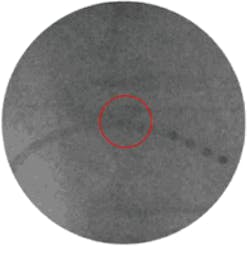
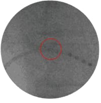
Unlike the human visual system (HVS), many current machine-vision systems are unable to interpret the contextual information within images. Only by examining images in a wider context can features be discerned. In such a wide context, for example, the stent in a low-dose x-ray image is clearly discernable by the HVS (see Fig. 1). However, when no contextual information is taken into account, the stent cannot be detected.
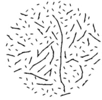
Human beings are able to use contextual information intelligently to fill in missing information. For instance, given only a number of separated line elements, structure seems to become apparent and line elements are fused into lines. Although this type of contextual information is critical in many applications, classical machine-vision algorithms usually discard this valuable information.
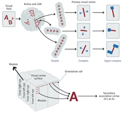
Research on how the HVS processes the data by Nobel Prize winners David H. Hubel and Torsten N. Wiesel reveals that images captured by the retina are transmitted through the optic nerve to the brain’s visual cortex. In the primary visual cortex, simple cells become active when they are subjected to stimuli such as edges (see Fig. 2).
Complex cells then combine the information of several simple cells and detect the position and orientation of a structure. Hyper-complex cells subsequently detect endpoints and crossing lines from this position and orientation information, which is then used in the brain’s secondary cortex for information association.
To model the HVS, Drs. Remco Duits, Erik Franken, and Markus van Almsick from the Eindhoven University of Technology recently developed a framework known as orientation scores. Captured images are first convolved with a number of generalized wavelet transforms oriented in different directions (see Fig. 3). This results in a stack of images, each of which contains local directional information within the original image.
This 3-D image data set can be seen as an energy map of the different local gradients or edges within the image and can be graphically depicted to show crossing lines appearing at different levels (their direction is different) in the 3-D map. The stack of images is then analogous to the complete set of complex cells in the HVS that contains information about location and orientation of edges. The detection of endpoints and crossing lines done by hyper-complex cells in the HVS is modeled by special operations on the orientation scores called G-convolutions, which consist of 3-D rotating kernel operations.
A winning idea
At VISION 2010, held in Stuttgart, Germany (Nov. 9–11), Dr. Frans Kanters, president of Inviso, showed how his company had developed a system, dubbed Inviso ImageBOOST, that uses these principles to perform high-speed analysis of image data. Developed in collaboration with the Eindhoven University of Technology, Inviso ImageBOOST is a standalone system consisting of a Camera Link interface and two Gigabit Ethernet interfaces, an embedded Virtex-5 XC5VSX50T FPGA from Xilinx, and up to 4 Gbytes of SODIMM memory.
Kanters and his colleagues implemented the orientation score framework on the Virtex-5 FPGA where the highly parallel nature of the FPGA implementation in the Inviso ImageBOOST system resembles the level of parallelism seen in the processing of visual information in the HVS. This information is then used by the secondary cortex (which can either be implemented in software on a PC or also on the FPGA) to perform selection, enhancement, and measurement functions.
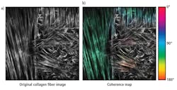
In applications such as visualizing the orientation of microscopic collagen fibers in tissue, the system is especially useful (see Fig. 4). After the original image (Fig. 4a) is processed, color is used to show the orientation of the bundle, with the saturation of the color representing the level of coherence of the fibers (Fig. 4b).
FIGURE 4. In applications such as visualizing the orientation of microscopic collagen fibers in tissue, the system is especially useful. After the original image (a) is processed, color is used to show the orientation of the bundle, with the saturation of the color representing the level of coherence of the fibers (b).
Using the algorithm, it is easily seen that parts of the image with low saturation do not have a common orientation but are more randomly distributed than parts of the image with high saturation. This results in the energy spread evenly over the orientation axis for randomly distributed fibers and energy localized in few layers of the orientation score for parts of the image with one common orientation.
To market the system, Kanters and his colleagues are looking to license the FPGA-based code to third-party peripheral vendors of smart cameras, frame grabbers, and embedded systems. Besides the orientation of microscopic collagen fibers in tissue, there are other applications that can significantly benefit from Inviso’s ImageBOOST unparalleled speed and quality in image analysis.
Using the algorithm, it is easily seen that parts of the image with low saturation do not have a common orientation but are more randomly distributed than parts of the image with high saturation.
Company Info
Eindhoven University of Technology
Eindhoven, the Netherlands
www.tue.nl
Inviso
Eindhoven, the Netherlands
www.inviso.eu
Xilinx
San Jose, CA, USA
www.xilinx.com
More Vision Systems Issue Articles
Vision Systems Articles Archives
