Video imaging system tracks targets on missile flights
Dual-video-camera tracking systems automatically identify and process target trajectories based on programmable cueing parameters.
By John Haystead, Contributing EditorMeasuring the accuracy and performance of sophisticated weapon systems, such as guided missiles and anti-aircraft systems, requires precise target tracking and miss-distance analysis. Collecting these data can be costly, particularly when on-board sensors and telemetry equipment are destroyed during testing.
Imago Machine Vision (Ottawa, Canada) is addressing this need with its PC-based Imago 100 video target-tracking and miss-distance analysis system. This system, demonstrated by the Canadian Army and Air Force and the US Navy, can track unmanned aerial vehicles (UAVs) and missiles. In a recent Stinger missile trial, for example, the system tracked missiles fired at 30-s intervals from launch to intercept.
"[The company] recognized some opportunities for machine-vision technology in the military's testing programs," says Terry Folinsbee, Imago vice president of engineering. "In some cases, users needed a more-capable tracker, or, where they had collected videotape from hand-held or manually controlled cameras, image stabilization was required to get the level of detail needed for complete image analysis," he adds.
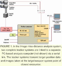
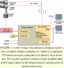
FIGURE 1. In the Imago miss-distance analysis system, two complete tracker systems are linked to a separate PC-based analysis computer (not shown) via a serial link. The tracker systems transmit target-position data and images taken at the target/weapon system point of closest encounter.
During Imago 100 operation, two video-tracking systems are used (see Fig. 1). The trackers are linked to a separate, remote miss-distance-analysis computing system via an RS-232 serial link. This setup allows test data to be processed and analyzed while the trackers continue with live operations. Other data-link options, such as microwave and fiberoptic cable, can be used depending on the configuration required. An inter-range instrumentation group (IRIG) time-synchronization signal is also carried between the two trackers.
The video-camera configuration of each tracking system varies depending on user requirements, but typically both trackers are equipped with separate cameras for acquisition and tracking. In cases for which only a limited range of focal length or field of view is needed, a single camera or a camera with a zoom lens can be used. For example, in Canadian Service missile trials, a dual-camera system was used, whereas anti-aircraft trials required only a single-camera system.
The video cameras are SSC-M370 monochrome CCDs from Sony (Park Ridge, NJ). Equipped with electronic shutter control, the cameras automatically adjust exposure settings to suit a range of lenses and lighting conditions. Monochrome images are collected at 640 x 480 x 8 resolution. Follinsbee says this resolution is adequate because the system typically tracks targets as small as a single pixel, although it is preferable to have a larger marker where possible. Because the field of view is controlled by the choice of lens (longer lenses are used for more distant targets), target image size can be kept relatively constant.
FIGURE 2. Tripod-mounted Imago 100 pan/tilt unit is configured with two video cameras. The cueing system accessory for the tracker system consists of a pair of binoculars and an integrated electronic compass mounted on a pan/tilt module and interfaced to the computer system via an RS-232 serial link. Slaved to the binocular system, the tracker enables the spotter to find the target. Then, compass bearing and elevation data are automatically transmitted to the tracker computer.
The cameras pass RS-170 image data to a combined frame gabber/ image-processing board built by Matrox (Dorval, Quebec, Canada). This Image LC board hosts a Texas Instruments (Dallas, TX) TMS5324020 DSP and an onboard arithmetic logic unit for point-to-point operations. Using software-selectable switching, the single Matrox board services multiple cameras, digitizes analog inputs up to 20 MHz, and carries a software-programmable 3-Mbyte frame buffer. After capturing the data, the board also performs initial signal-processing functions such as thresholding, blob analysis, profiling, and segmentation to identify one or more potential targets. This single-slot PC-AT board is housed in a rack-mounted industrial Pentium PC supplied by ICS Advent (San Diego, CA) with a built-in monochrome monitor.
Target acquisition
In a basic Imago miss-distance system, the operator acquires the target by manually controlling the direction of the acquisition camera using a joystick. Then, after positioning the target somewhere in the camera's field of view, control is handed off to the automated tracking system. This initial target acquisition can be handled electronically using an automated cueing system such as an instrumented binocular system or a radar system, if available.
Imago provides its own cueing-system accessory for the tracker system. It consists of a pair of binoculars and an integrated electronic compass mounted on a pan/tilt module and interfaced to the computer system via an RS-232 serial link. The binoculars can be hand-held or tripod-mounted (see Fig. 2). Slaved to the binocular system, the tracker allows the spotter to find the target, and compass bearing and elevation data are automatically transmitted to the tracker computer.
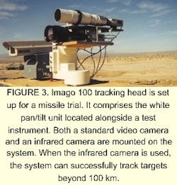
FIGURE 3. Imago 100 tracking head is set up for a missile trial. It comprises the white pan/tilt unit located alongside a test instrument. Both a standard video camera and an infrared camera are mounted on the system. When the infrared camera is used, the system can successfully track targets beyond 100 km.
According to Folinsbee, binocular cueing systems must be connected to one or both tracker systems, depending on the test parameters and range configuration. To prevent offsets in bearing information, the cueing system must also be located in close proximity to the tracking camera. Consequently, a single cueing system can be used only when the two trackers are positioned close to each other relative to distance to target and the bearing between both trackers is not largely different. Alternatively, a single radar system can be used to cue any number of trackers with no restrictions on their relative positions.
Once activated, the automated tracking system initially identifies and automatically locks onto possible targets based on visual cues. Individual image frames are processed by the Matrox board to cull out pixel combinations corresponding to a set of preprogrammed parameters. Preprocessing includes spatial edge enhancement, neighborhood clutter suppression, and automatic bipolar contrast detection. Users also have the option of tracking the leading, trailing, top, bottom, and left or right edge of the target.
Follinsbee says, "Target-identification parameters are deliberately kept fairly generic, with a standard parameter set able to identify 95% of the targets we might be tracking." This approach eliminates the need to reprogram the system for each target type or for direct operator intervention during the tracking process. " In typical applications, both target size and appearance undergo large changes over short periods of time, and operators do not have the time or the experience level necessary to make rapid adjustments during an actual test," he adds.
Some cueing parameters can be adjusted to suit certain targets, test-range environments, or applications, however. For example, the size of objects that the system is trying to find and to identify as targets can be modified. This is a useful feature for close targets that often fill a large part of the field of view. The threshold level at which the "brightness" or intensity of an object is classified as a target can also be adjusted. However, lowering the threshold level to increase the system's ability to identify small or distant targets must be balanced against the increased likelihood that false targets will be identified.
The amount of smoothing applied to the target-position data during processing can also be reduced. This condition improves the system's response time and benefits the tracking of high-acceleration targets.
Target tracking
The target-characteristic data generated by the Matrox board are further processed and analyzed by the tracker system's Pentium processor. Although all of the computationally intensive (pixel-level) image processing is handled by the DSP processor on the Matrox board, higher-level, follow-on operations are handled by the tracker system's PC processor. For example, in cases where more than one possible target is initially identified in a frame, the system determines the correct object by comparing the position and appearance of each object in subsequent frames against the predicted pattern of motion or direction of travel that the actual target would be expected to follow. By correlating these data with previous tracking information, the system can predict the location at which the target will appear in each subsequent frame and then look for the best match.
The system performs 90% full-screen processing, which ensures continued tracking even when the target is occasionally lost. Using standard video cameras, the system has successfully tracked UAVs at ranges of 15-20 miles using a 1000-mm lens where, at the extreme range, the target was usually not large enough for the system to discern from background clutter (see Fig. 3). Described as a "subclutter point" in the camera imagery, the UAV was only sporadically recognized by the tracking system against background clutter. Nevertheless, it was tracked.
The tracker PC processor continuously controls the position of the pan-tilt unit, recording its orientation at the time each image is collected. The pan/tilt unit is a commercially available system used primarily by the television industry. "Although the tracker system is precise in its pointing direction, it wasn't designed for real-time tracking; to compensate for this shortcoming, the tracker incorporates pan/tilt modeling software to optimize control and accuracy," says Folinsbee. The pan/tilt unit has an internal server loop that performs detailed server motor control with the tracker sending only a basic RS-422 serial command stream.
Live imagery is displayed on a separate Sony PVM 1350 13-in. RGB monitor with a cursor indicating the target. An overlay screen also shows time of day, target position, and azimuth and elevation data. This information is recorded on the tracker system's computer hard disk while the processed video imagery is captured on videotape. Together, the image and data files constitute a log-file of the test.
Analysis system
The log-files from both tracker systems are transmitted via a data link to a remote analysis system either in real time or as a batch transmission after the test is completed. A Matrox Meteor PCI frame grabber in the analysis system computer redigitizes pertinent videotape images. This processing might consist of only a few frames centered on the time at which the target and weapon system flew past each other. As explained by Follinsbee, redigitization is necessary because, although the images were initially digitized during the actual target-tracking phase, those data were immediately processed and discarded.
The analysis system then calculates the precise position of the targets in each frame using the data file supplied by the tracker. The data are processed using triangulation algorithms to determine the precise separation between the target and the weapon system at the point and time of their closest approach.
Typically 5 to 10 minutes are required to determine the miss-distance for weak targets; accuracy depends on both the separation distance of the trackers and the distance from the trackers to the target. Accuracy increases when the trackers are located farther apart and decreases as the angle increases between the target vehicle flight path and the tracker line of sight. In one Canadian Army missile trial, the two trackers were positioned with an intercept point of about 45° and a range-to-target of 2 km. The calculated miss-distances agreed within 0.8 m with the measurements from an on-board miss-distance indicator that had an accuracy of 1 m.
The miss-distance system can also operate in real time with no post-analysis necessary. Therefore, configuration-tracking data from the two trackers are transmitted to the analysis system during the actual encounter.
Software algorithms
The photogrammetric software algorithms for both the tracking and analysis systems are written in a combination of Visual C and C++. Imago uses the Matrox Image Library (MIL) and low-level calls for time-critical functions performed by the tracking system's image-processing board. The programming library includes a set of optimized functions for image processing, pattern matching, blob analysis, gauging, OCR, acquisition, transfer control, and image-compression/ decompression. "We use the standard image-processing functions supplied in the high-level image-processing library. These tools program the board so we don't have to worry about low-level programming, although the algorithms we use have to be tailored to the capabilities of the board to some extent," says Folinsbee.
The user interface on the tracker system is DOS-based whereas the miss-distance analysis system software runs under Windows NT. Imago is developing a next-generation Windows-based version of its tracker system that will also incorporate the Matrox Genesis image-processing board. Each of the Genesis board's multiple processing nodes includes a parallel TMS320C80 DSP to process video streams and a custom neighborhood processor that performs simultaneous pixel-by-pixel processing to rapidly compare relative values in a particular pixel block. A separate ASIC manages all the data I/O functions. Processing nodes can be configured in either parallel or pipeline topologies.
Company Information
ICS Advent
San Diego, CA 92121
Web: www.icsadvent.com
Imago Machine Vision
Ottawa, Ont. K1Y 3C3 Canada
Web: www.imago.on.ca
Matrox
Dorval, Quebec, H9P 2T4 Canada
Web: www.matrox.com
Sony Electronics
Park Ridge, NJ 07656
Web: www.sony.com/videocameras
Texas Instruments
Stafford, TX 77477
Web: www.ti.com/dsps


