IR cameras inherently measure irradiance not temperature. The camera’s software converts these radiance measurements into temperatures by using the emissivity of the object and applying internal calibration data for the camera’s spectral response. Transparent materials, whose emissivity varies strongly with wavelength, such as glass and many plastics, tend to be selective radiators and their degree of transparency varies with wavelength. Since, according to Kirchhoff’s Law, a good absorber is also a good emitter, the radiance and temperature of selective radiators can be measured at some specific wavelength.
Inserting a spectral filter into the camera’s optical path is called spectral adaptation. First, the spectral properties of the target to be measured must be found. For common materials this may already be available. Otherwise, a spectrophotometer must be used to provide this data. In either case, the spectral absorption band for the object must be found.
Although microbolometer detectors have broad response curves, adding a filter decreases overall sensitivity. This can pose a problem, since microbolometer-based detectors have relatively low sensitivity and broad spectral curves. Using a camera with, for example, a QWIP detector provides greater sensitivity but the camera’s narrow spectral range may limit the application of such cameras for spectral adaptation.
Optical filters
In spectral adaptation, filters are used to suppress or transmit certain wavelengths. These filters can be short-pass (SP), long-pass (LP), bandpass (BP), and narrow bandpass (NBP). SP and LP filters are specified with a cut-on and a cut-off wavelength. BP and NBP filters are specified with a center wavelength and a half-width (half-power) wavelength, the latter being the width where spectral response has decreased to 50% of its maximum.
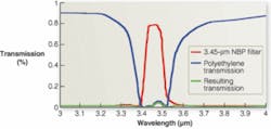
NBP filters can be used in the measurement of polyethylene film (see Fig. 1). While the blue curve shows the absorption band of the film, the red curve shows the transmittance of a 3.45-µm NBP filter, designed to match the polyethylene film. The green curve shows the resulting transmission through film with the filter. This curve, running just above the zero line, indicates an excellent filter adaptation; the film appears to be opaque to the camera, and no background radiation disturbs film temperature measurement.
FIGURE 1. NBP filters can be used in the measurement of polyethylene film. A filter achieves nearly complete absorption and high emittance from the film, allowing its temperature to be measured.
Filters can also be classified according to their application temperature. Traditionally, cold filters that are stabilized at or near the same temperature as the detector are the most accurate for thermal signatures. Warm filters, filters screwed onto the back of the optical lens outside of the detector/cooler assembly, can also be used but tend to require more radiometric calibration due to varying IR emission with ambient temperature changes.
To obtain an emissivity value (ελ), transmittance (τλ) and reflectance (ρλ) at the pass band of the filter must be known
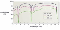
While transmittance can be obtained taken from a transmission diagram, reflectance is more difficult to characterize and is usually a function of a material’s thickness. However, a transmission diagram provides some indication of this parameter’s value (see Fig 2).
Using the blue curve for the thinnest polyethylene material, which has the lowest absorption, the transmission between absorption bands is approximately 90%. If there were no absorption bands at all, the reflection would be 10%. Since there are some narrow absorption bands under the curve, the reflection is approximately 8% in the spectral regions where absorption is low. However, where the absorption is high (where the material appears to be opaque), it must be assumed that the surface reflectance stays constant over the absorption bands and the 8% reflection value is the result of reflections from both sides of the film, that is, approximately 4% per surface. At the absorption band, however, since the absorption in the material is almost complete, there is reflection only on one side. Thus ρλ = 0.04.
From this, the ρλ, and the τλ value obtained from the transmission graph of Fig. 3, emissivity can be calculated as
This value is entered into the camera’s measurement database before temperatures measurements from radiance observations are made.
Sheet glass
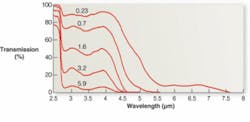
Sheet and plate glass have similar temperature-measurement requirements. The most common industrial varieties are variations of soda-lime-silica glass. Although they may vary in composition and color, their spectral characteristics do not radically change. Examining the spectral transmittance of this glass for different thicknesses, one can conclude that IR temperature measurement must be restricted to wavelengths above 4.3 µm (see Fig. 3). Depending on glass thickness, this may require either a midwavelength (MW) or long-wavelength (LW) camera/detector. MW cameras cover some portion of the spectrum from 3 to 5 μm, and LW cameras cover some portion between 8 and 12 μm.
FIGURE 3. Examining the transmission curves for a common industrial glass in five thicknesses from 0.23 to 5.9 mm allows the conclusion that IR temperature measurement must be restricted to wavelengths above 4.3 µm.
In selecting a filter, one might choose a LP type with a cut-on wavelength near the point where transmittance drops to zero. However, LP filter characteristics can interfere with the negative slope of the spectral response curve of thermoelectrically cooled HgCdTe (MCT) detectors, which are used in both MW and LW cameras. For this reason an NBP filter may be a better choice.
There are many applications where the user needs to find a spectral band where the medium through which the camera is looking has minimum influence on the measurement. In most cases, the medium is the atmosphere, but it could be a gas or a mixture of combustion gases or flames, a window, or a solid semi-transparent material.
In most cases, IR camera manufacturers have anticipated the atmospheric attenuation problem. They typically add a filter that reduces measurement errors due to inaccurate and/or varying atmospheric parameters by avoiding absorption bands of the constituent gases and water vapors. This is especially needed at long measurement distances and shorter wavelengths. For MW cameras, an appropriate filter uses the atmospheric window between the absorption bands of H2O + CO2 around 3 µm, or CO2 at 4.2 µm.
Atmospheric effects on an LW camera are smaller, since the atmosphere has a window from 8 to 12 µm. However, cameras with a broad response curve reaching into the MW spectrum may require an LP filter. This is particularly true for high temperature measurements where the radiation is shifted toward shorter wavelengths and atmospheric influence increases. An LP filter with a cut-on at 7 µm blocks the lower part of the camera’s response curve.
Gas furnaces
In temperature measurements of a gas-fired furnace, flame-temperature measurement or measurement of internal components may be required. In the latter case, an unfiltered IR camera will be overwhelmed by the intense radiation from the flames, making measurement of the much weaker radiation from internal objects impossible. On the other hand, any transmission through the flames from cooler internal objects will make flame temperature measurements inaccurate.
The flame absorption spectrum reveals the spectral regions where these two types of measurement could be made. There is very little radiation from the flames in the 3.9-µm region, whereas there is a lot of radiation between 4.2 and 4.4 µm. Filters must use these spectral windows for the desired measurements.
For measurement of internal components, strong absorption bands need to be avoided because they attenuate the radiation from the target object and emit intensely due to the high gas temperature, thus blinding the camera. Although gas-fired combustion gases consist mostly of CO2 and water vapor, an atmospheric filter is unsuitable because gas concentrations and temperatures are much higher. This makes the absorption bands deeper and broader.
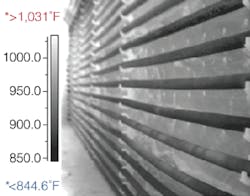
A 3.9-µm flame filter is needed for this application. This is a BP filter transmitting between 3.75 and 4.02 µm. With this filter installed the camera will produce an image where the flames are almost invisible and the internal structure of the furnace is presented clearly (see Fig. 4). To obtain the maximum temperature of the flames, a 4.3-µm CO2 filter will show they are as high as 1400°C. By comparison, the furnace walls as seen with the flame filter are a relatively cool 700°C.
FIGURE 4. FLIR ThermaCAM imaging of furnace tubes with flame filter achieves accurate temperature measurement.
Filters can extend the application of IR cameras into areas that might otherwise restrict their use. Still, some preliminary spectrophotometer measurements may be needed on the targets and media of interest if spectral information cannot be found in IR literature. Once a filter is selected and installed, the camera/filter system should be calibrated by the camera manufacturer. Even with a well-calibrated system, is a good idea to avoid errors by avoiding spectral regions of uncertain or varying absorption relative to the camera/filter system response spectrum.
David Bursell is director, Science Segment, at FLIR Systems, North Billerica, MA, USA; www.flirthermography.com.


