Machine vision automates jewelry-part inspection
Vision sensor and software check gold earring backs for dimples.
By David Lieberman, Contributing Editor
A New York manufacturer of jewelry castings and settings has been manually inspecting its die-struck parts for about 50 years. It has been an accurate but very time-consuming process that was very tiring on the eyes and extremely tedious. The company is now automating parts of its manufacturing process and relies on a machine-vision system to determine whether or not the dimple (or “pinprick”) on a 1/4-in.-sq gold earring back is near the center.
If the dimple is mispositioned more than about 5/1000 in. there could be problems in the next manufacturing step, which consists of automated crimping. And if the dimple is missing altogether, the forming punch breaks. The decision to automate the process was driven by the convergence of declining prices for vision systems and growing demand for jewelry.
DIMPLE IMAGING
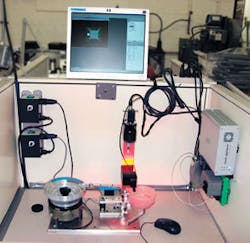
The vision subsystem of the dimple-locating equipment was developed by Faber Associates-an application solutions provider. The foundation of the machine-vision design is a vision sensor from DALSA IPD. The inspection station fits within a single-person cubicle, with much of the equipment mounted on the sides and back of the cubicle walls.
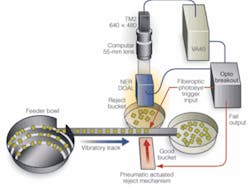
The system has a vibratory bowl that feeds parts down a vibratory track, single file, to be inspected. The mechanics of the system ensure that the parts are right side up and all lie within the same orientation. After an earring back is inspected, if the vision subsystem gives it a passing grade, the part continues down the track until it falls into a collection bowl containing good parts, which will later be fed to the automatic crimping machine. If a part fails, either because the dimple is missing or is located in the wrong position, a pneumatic-actuated pusher is triggered that sends the part into a bowl of rejects.
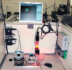
The dimple-analysis system is based on a VA40 vision appliance from DALSA mounted to the upper right of the inspection station (see Fig. 1). The appliance’s embedded computer contains all of the hardware and software that are required to capture, process, and display images. The VA40 also can handle communications, networking, user interface, and industrial I/O, and it runs the software that analyzes images to determine whether parts are good or bad.
The VA40 I/O includes RS-232 serial, parallel, 10/100-Mbit/s Ethernet, audio, and dual USB 1.1 interfaces, with three 15-pin interfaces provided for as many as three progressive-scan analog cameras. The system’s 24-Vdc DIN mount power supply is in the rear right corner of the cubicle.
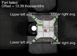
The software, preloaded onto the VA40 40-Gbyte hard disk drive, is Sherlock, a general-purpose image-processing package from DALSA IPD, optimized for automated inspection applications. As the earring back travels along the vibratory track, Sherlock displays the live image, gives a visual and numeric indication of the dimple offset, and indicates the average dimple position for the inspection run (see Fig. 2). A bright red circle on the track from a red LED, delivered by an optical fiber, serves as a trigger signal for image capture.
Among the other key components of the vision system is a CS8550Di-50 monochrome digital camera from Toshiba Teli, with a TEC-55 nearly telecentric lens from CBC (America). Based on a 1/3-in. CCD, the camera is a miniature (1 × 1 × 1.5 in.), high-speed (60 frames/s), VGA-format (640 × 480 pixel), progressive-scan, monochrome device. It sends the images over a analog video link to a frame grabber on the IPD VA40 for display, analysis, and decision making. A telecentric lens-about twice the cost-was not necessary for this application, Raciti says.
LIGHTING AND LAYOUT
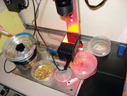
Between the camera and the vibratory track of the dimple inspector is a 50-mm diffuse on-axis light (DOAL) from Siemens Energy & Automation/NER (see Fig. 3). DOALs are designed specifically to deliver diffuse, uniform light onto flat, specular surfaces such as the earring backs on the vibratory track. “The DOAL gives very even illumination on these bright shiny parts,” says Raciti. “If they had chosen ringlighting instead, you’d be able to see the ring on the shiny parts.”
The DOAL is a Nerlite DOAL-50 V2 Series device, housed in a black anodized aluminum case. In it the light emerging from a red LED is directed horizontally onto a beamsplitter, which directs the light down onto the vibratory track at about a 90˚ angle, matching the optical path of the camera. The camera has a direct perpendicular view of the parts on the track through the two-way mirror of the DOAL. In operation, specular surfaces that are at perpendicular to the stream of light appear bright to the camera. Angled surfaces and nonspecular surfaces, in contrast, appear to be dark.
Trigger and reject mechanisms comprise a WLL 170-2 fiberoptic photoelectric sensor/switch from SICK and an air-actuated solenoid, both integrated with the track. To communicate with these subsystems, the VA40 relies on an isolated digital I/O subsystem from Grayhill, which interfaces via a 25-pin device for general-purpose I/O. The subsystem consists of a 70LRCK16-HL-DIN breakout rack, with two 24-V OpenLine modules, each providing four digital inputs and four digital outputs.
The module shines a steady red light up through the core of an optical fiber and on out through the track. When a part passes over the light, its specular surface reflects the light back to the module, where the photons are sensed around the outer edges of the fiber (see Fig. 4). This triggers the camera to capture an image, with the signal traveling first to the breakout box and then on to the VA40-all in time to view, analyze, and judge the images before the parts reach the reject mechanism.
features, advantages, benefits
According to Greg Raciti, engineering manager at Faber Associates, the earring-back inspection system is a simple device. “It was mind boggling to watch them manually going through thousands and thousands of parts, piece by piece,” he says. “They were able to discern an offset [of the dimple from the center] by maybe 6 or 7 thousandths of an inch, but it took forever.”
“Now,” says Raciti, “all that’s required is that they take a look at the equipment every so often to make sure nothing’s jammed up from a mechanical standpoint. The real magic of the new system, what makes it simple, is its very robust handling system and using the right lens and lighting.”
