Telecentric lens-based machine-vision systems profile diamond grinding wheels
Valerio Riva and Andrea Varisco, Cafro; and Claudio Sedazzari, Opto Engineering
Diamond grinding wheels are widely used for precision mechanical component finishing in aerospace and automotive applications. Both the part being machined and the tool used to machine the part must be inspected during fabrication since the tool itself consists of a diamond grinding wheel that wears while the part is machined. During manufacturing, both parts and tools are inspected manually by workers who carefully analyze the wheel profile being machined using an optical profile projector. These projectors enlarge the view of the part and the tool, and display an image of the part on a diffusive screen on which the image can be manually measured. Because the process is performed optically, no images are stored during the inspection procedure.
In performing this optical inspection, a number of manual operations are required to ensure the correct part profile is produced. First, an initial profile of the part must be defined and a 1:25 scale contact paper drawing must be prepared. After this contact paper drawing is aligned inside the projector, the optical magnification of the system must then be manually adjusted. In addition to being time consuming, several factors negatively affect the measurement accuracy and efficiency of the system. These include relatively low image brightness and resolution, a maximum wheel diameter of 250 mm, and a maximum part profile width of 20 mm. Just as important, because the system uses a halogen light source to illuminate the part, the lifetime of the bulb is short, requiring frequent replacements, and power consumption is high. To add to these disadvantages, the contact paper is subject to expansion caused by humidity and temperature, and parallax error and optical distortion introduce errors in measurement.
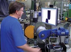
To overcome these problems, Cafro, a diamond tool manufacturing company, and Opto Engineering have developed a machine-vision system that uses both a collimated LED light source and a telecentric lens coupled to a digital camera (see Fig. 1). In operation, a green LED light is projected by the collimated light source onto the diamond grinding wheel and the light is captured by a 1/2-in. XVGA FireWire camera coupled with a telecentric lens. The resulting image is then captured, stored, and displayed on an XVGA monitor of a host computer.
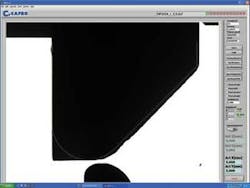
Because the system uses collimated LED lighting, the optical efficiency of the digital system is higher than the previously used projection system. Replacing the incandescent lamps previously used also results in a more stable light output, resulting in an even illumination of the part. In turn, this allows the edges of the diamond grinding wheels to be more accurately determined. Moreover, the combination of a collimated light source and a telecentric lens yields an optical system with high resolution, low distortion, and large depth of field, making an accurate determination of the edges of the part more reliable (see Fig. 2).
FIGURE 2. Combining a collimated light source and a telecentric lens yields an optical system with high resolution, low distortion, and large depth of field, making an accurate determination of the edges of the part more reliable.
Because the system employs a machine-vision system, the machining process is made both faster and more accurate. Profile drawings can be edited using CAD software and imported, stored, and modified to produce a reference model that can be displayed on the PC screen and overlaid onto the part being machined.
To produce the correct part profile, the grinding wheel is mounted on a motorized stage and brought into contact with the cutting tool. This motorized stage turns the part and its position at every stage is measured by an optical encoder. By viewing the part being machined, the overlay of the CAD drawing, and the cutting tool, the operator can accurately visualize how to accurately machine the part (see Fig. 3).
Using the system, wheels with diameters of up to 750 mm and 120 mm in width can be machined. This is made possible by the use of the system’s telecentric lens that eliminates any parallax error. In addition, the system can be verified, calibrated, and adapted to different machines or production lines.
Valerio Riva and Andrea Varisco are with Cafro, Como, Italy, www.cafro.com; and Claudio Sedazzari is with Opto Engineering, Mantova, Italy, www.opto-engineering.com.


