Rotary-actuator driven laser-line projectors reduce potential occlusions and speed 3D-point-cloud acquisition.
Many job shops and factories have deployed robotic bin picking to automate material handling operations. A typical bin picking system includes a robotic manipulator, a 2D or 3D machine vision system, and control software. The robot, guided by the machine vision system, picks up objects from a container and places them on a conveyor, into a process, machine tool, or at predefined positions on a pallet or part carrier.
Compared to conventional automation systems, robotic bin picking helps manufacturers to streamline their production and protect workers from hazardous and repetitive tasks. It also minimizes reliance on costly precision fixtures and provides the ability to process various part types without tooling changeovers.
By managing various parts with the same automation system and picking parts directly from storage containers, manufacturers can reduce costs, increase flexibility, while minimizing the time and resources needed to design and build fixed tooling and other mechanical systems for each type of part or product being processed.
Types of bin picking
Based on part geometry, material characteristics and required cycle time, manufacturers typically deploy structured, semi-structured or random bin picking. In structured bin picking, parts are predictably stacked in the bin. Semi-structured bin picking organizes parts in the bin to assist imaging and picking. Random bin picking has parts piled haphazardly in various orientations.
While structured and semi-structured bin picking applications are generally simple enough to be readily addressed with a conventional 2D machine vision system, random bin picking typically requires a 3D machine vision system. Since overlapping and potentially interlocking parts within the bin demand more advanced 3D machine vision technology, such applications tend to be more expensive, and more often involve a system integrator knowledgeable of 3D imaging techniques including stereo-camera implementations, systems that employ structured-laser light and projected-pattern-based lighting.
>>> GET PRICING.
While each of the aforementioned 3D imaging techniques has pros, cons and price-performance tradeoffs, the use of laser displacement sensor technology, combining a line laser and area scan camera, has several advantages especially for random bin-picking applications that may involve picking a variety of different colored parts ranging from matt and dark colored material to partially shiny objects.
Laser profiling systems
According to Nicolò Boscolo, Account Manager and European Projects Manager for IT+Robotics (Padua, Italy; www.it-robotics.it), this is because laser profiling systems are “more robust to ambient light sources when compared to random- or striped-pattern light projectors due to the higher power laser light that is focused on a narrower area. Also, compared to stereo-vision-based systems, laser triangulation performs better when dealing with objects that have limited surface texture or patterns.”
There are a couple of tradeoffs, however, Boscolo notes. “First, the scanning time can be greater than stereo or projected-pattern technologies, ranging from 1 to 2 seconds, depending on the required resolution. However, if the scanning takes place while the robot is not working over the bin, which is usually the case, this should not affect the total cycle time. Another trade-off is that laser profiling systems require linear motion for either moving the laser over the parts or for moving the parts under the laser.”
That is why such solutions are not typically directly provided by laser profiler producers to end users, but rather, Boscolo explains, are “installed by system integrators.” However, according Boscolo, this approach involves “high-risk costs charged on the final user, that may ultimately put this technology out of reach for small and medium-sized enterprises.”
To address this issue, engineers at IT+Robotics have developed a unique 3D machine vision system called EyeT+ Pick, which integrates a motor pack with two lasers and a camera. The device has recently been honored with a Silver-level 2018 Vision Systems Design Innovators Award.
“To solve these problems, EyeT+ Pick was designed with two main goals in mind. “First, to reduce integration costs, installation of the device has to be easy for system integrators,” Boscolo explains, “and second, the configuration has to make it very easy for the final users during production reconfigurations in order to minimize the required resources, changeover times and the associated costs.”
Rotary vs linear actuation
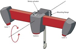
EyeT+ Pick relies on an integrated rotary actuator from Oriental Motor (Torrance, CA, USA, www.orientalmotor.com), which pivots the camera and dual-laser assembly about its roll axis. A camera from Photonfocus (Lachen, Switzerland; www.photonfocus.com) is centered between the two the two laser-line projectors from Laser Components (Olching, Germany; www.lasercomponents.com), with the lasers angled slightly towards the camera’s optical center (Figure 1).
Figure 1: The use of a rotary actuator in the EyeT+ vision device provides compact design that reduces vibration and mechanical stress when compared to linear axis systems.
The integrated rotary actuator design has several advantages over the use of a conventional laser displacement sensor with separate linear axis, according to Boscolo. “Rotary motion provides a more compact structure than linear, dramatically reducing system cost and required work-cell space,” he explains. “Moreover, the smooth rolling motion reduces vibrations and mechanical stress on the vision system, increasing operating life, and the provided flange makes positioning the device within the working area fast and easy.”
Two lasers better than one
During operation, as the laser line scans across the field of view, the camera acquires the 3D point cloud and the device then transmits the data to a high-performance industrial PC with 4.0 GHz Intel i7 core from Neousys Technology (Taipei City, Taiwan; www.neousys-tech.com) running IT+Robotics’ Smart Pick 3D Solid software.
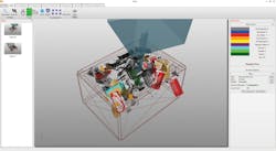
The vision device provides an accurate 3D view of the container while the software tackles the two main problems related to bin picking, Boscolo explains. “First, it accurately detects the 3D pose of the object inside the bin. Then it defines the trajectory, which tells the robot how to reach the product and grasp it avoiding collisions with other products or the bin.”
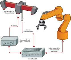
Figure 2: Smart Pick 3D software runs on an industrial PC linked via standard industrial communication protocols to the other system components.
Compared to systems with a single laser line projector, two lasers make EyeT+ Pick twice as fast and more robust against occlusions and shadows caused by part geometry according to Boscolo noting, “basically, blind spots with respect to one laser are likely to be captured by the other. Moreover, the dual laser technology creates a dense and accurate point-cloud helping the Smart Pick 3D Solid algorithms to perform a fast product recognition and localization to cover bin-picking applications with cycle times as low as four seconds.”
>>> GET PRICING.
Ease of use
After installing the EyeT+ vision device over the picking area, Smart Pick 3D Solid is used to configure the main system components including the picking area, the robot, the products and the related grippers. Users define the size of the bin, add any eventual obstructions that may be present in the picking area and configure the manipulator by importing CAD models of the robot and gripper and then setting limits.
Robot kinematics are modelled in the Smart Pick 3D simulation core and the software uses the data to avoid robot singularities and reachability issues. The vision system connects the robot via the software’s server architecture that exposes commands that should be called from the robot, through a communication channel based on industrial fieldbuses such as Devicenet, Profibus, CANOpen, EthernetIP, EtherCAT, Profinet, and Siemens Snap 7 using PCI boards supplied by Beckhoff (Verl, Germany; www.beckhoff.com). For robotics and vision researchers using EyeT+, the company also supports ROS-Industrial interface (www.rosindustrial.org).
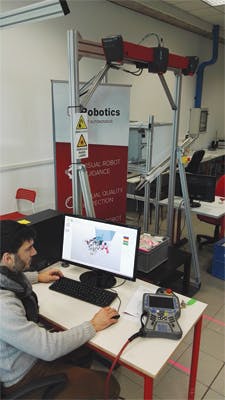
Figure 3: Smart Pick 3D scene reconstruction during production shows recognized products highlighted with green indicating the easiest and next best one to pick.
To share a common frame of reference between the vision system and the robot, calibration is required. The calibration procedure employs a checkerboard as reference frame and involves contacting a few points with a tip mounted on the robot to record the position.
“Usually the full calibration of the whole system takes less than 15 mins,” notes Boscolo. The communication interface is designed to be plug and play, using standard register-based industrial field bus communication that requires minimum programming effort on the robot. Also, when the installation is complete, the Smart Pick 3D Solid software provided with the system exposes a user-friendly interface to set-up new products in only two steps. First, users import the 3D CAD model of the parts or products, then they define the gripping points. The software computes robot trajectories to pick the product, while considering robot reach and collision avoidances. To further simplify the setup of the entire device, the provided software exploits the RS485 serial interface of the motor to manage the scanning cycle and the synchronization with the robot, without requiring PLC programming.
Companies mentioned:
Beckhoff
Verl, Germany
IT+Robotics
Padua, Italy
Laser Components
Olching, Germany
Neousys Technology
Taipei City, Taiwan
Oriental Motor
Torrance, CA, USA
About the Author

John Lewis
John Lewis is a former editor in chief at Vision Systems Design. He has technical, industry, and journalistic qualifications, with more than 13 years of progressive content development experience working at Cognex Corporation. Prior to Cognex, where his articles on machine vision were published in dozens of trade journals, Lewis was a technical editor for Design News, the world's leading engineering magazine, covering automation, machine vision, and other engineering topics since 1996. He currently is an account executive at Tech B2B Marketing (Jacksonville, FL, USA).
B.Sc., University of Massachusetts, Lowell
