Roll of the Die
GigE cameras and pattern-matching software track and inspect chips on a tape reel to maximize throughput
One of the largest backend semiconductor assembly operations in Bangkok, Thailand, recently turned to semiconductor-packaging-equipment supplier Datacon Technology and Besi North America, both part of BE Semiconductor Industries, to maximize the throughput of die-sorter machines. In these machines, individual unpackaged dies are inspected and then packaged in thermoseal tape prior to shipping for die or wire frame bonding.
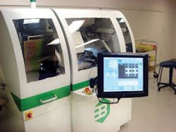
Placing fragile die between two plastic tapes is not a simple process. The die sorter must place the chips inside the tape with 25-µm precision and less than 1º rotation at rates of 16,000 per hour, or more than four parts per second (see Fig. 1).
Machine vision plays a critical role in maintaining the accuracy of the pick-and-place and quality of the packed chips during the tape-reel process. To accomplish this feat, Datacon uses 12 LED arrays, five Opteon cameras, and associated processing hardware running DALSA’s Sapera image-processing software to check the die for defects and guide robotic arms measuring less than an inch to pick and place the die with ≤25-µm precision.
Don’t make waves
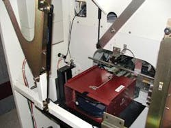
In the Thailand installation, operators deliver up to 25 trays of up to 300-mm wafers, each diced, to the first of three compartments in the CS1250 (see Fig. 2). The operator begins the sort, and the first image is acquired of the die inside the tray.
FIGURE 2. In the first of three compartments of the CS1250, up to 25 wafers can be loaded at a time.
Datacon chose Opteon’s camera and image-acquisition platform because it was one of the few systems with Gigabit Ethernet capability, global shutter sensors, 60-frame/s speed, and, most important, synchronized data delivery with 1-ms roundtrip from camera to processor to camera. According to Miroslaw Sokol, principal engineer for Besi North America, to achieve 16,000 units per hour, the CS1250 must generate the offset to guide a robot arm to a die within 1-ms round trip from the camera to the PC host, while the various inspection routines are accomplished in 5 ms. To reach this level of synchronization, Opteon offers proprietary machine interface devices (MIDs) to provide optoisolated camera control and strobe firing while meeting Besi’s latency requirements.
“We were developing the CS1250 when the DALSA Genie GigE camera first came out, but it was too late for our development cycle,” explains Sokol. For alignment purposes, Sokol used Opteon’s B1A 652 × 494-pixel resolution monochrome cameras, while the inspection tasks are handled by higher-resolution B2F 1004 × 1004-pixel resolution monochrome cameras. Both cameras are capable of delivering 60 frames/s with fast response and low latency.
The Datacon supervisory software running on a standard Windows XP-based PC host with 3.4-GHz single-core Pentium processor and Turbo PMAC2-PCI I/O card, triggers the Opteon MID to signal the camera to acquire an image and trigger two LED strobes. “We use 12 independent lights that are synchronized with the cameras because that’s the only way we could stop light bleeding from one camera to the next and degrading the images,” Sokol explains.
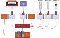
The B1A camera in the first compartment takes an overall picture of the diced wafer in the tray and passes the image to the MID, which transfers the image over standard CAT-5 GigE cable and then to the PC host. In host RAM, DALSA’s Sapera geometric pattern search locates the individual die on the tray in the image from Camera #1 based on previously stored vectorized descriptions of the die (see Fig. 3).
FIGURE 3. Datacon CS1250 tape reel sorter uses five independent cameras to control two proprietary pick-and-place robotic arms and conduct a number of quality inspections as it transfers dies from diced wafers to tape reels for shipping to final packaging.
Offset vectors are sent to a Turbo PMAC2-PCI from Delta Tau Data Systems to move the robot arm into position over the die. Using a vacuum end effector with soft polyurethane cup, the “pick” robot arm designed specifically by Datacon for low weight and fast action, picks the a die and places it on a “hand-off” location between the first two compartments. The Opteon MID triggers another bank of LED strobes, and a high-resolution B2F camera, called the hand-off camera (#2). This camera collects an image of the chip on the hand-off stage prior to being picked by the second robot arm (the placer arm).
Images follow this same transfer path, and the Sapera software conducts a pattern search to find the location of the chip on the hand-off stage. “We use Sapera’s geometric pattern feature for all the alignment actions, and the blob tool for all the remaining inspection routines, including edge and bump inspections,” Sokol, explains.
Pass the chips
The image from the hand-off camera, Camera #2, is also used for the first inspection tasks. “Inspections on the front include edge chipping, cracks, and solder bump inspection on the surface of the die, including presence, diameter and shape defects such as damage or a sheered bump that would effect operation,” says Sokol. “On the back, we’re looking for cracks, edge chipping, and chip ID marks to track each chip. Using the blob analysis, we find cracks, determine their position, width, height, and so forth, and use this information to qualify the effect on the chip, either pass or fail. The inspection data is written to both the portable digital file for the tape reel and to the local network in using Ethernet or SECS communication protocols (see Fig. 4).”
FIGURE 4. In addition to moving dies to a tape reel for shipping, the system performs front and back visual inspections of bumps, bonds, edges, and other features critical to a well-performing microchip.
Camera #2 tells the CS1250 the offset between where the die should be located on the placer end effector and where it actually is located. The offset then optimizes the robot path to place the die into the tape reel.
The MID triggers Camera #3, a standard resolution B1A camera called the “tape” camera, to capture an image of tape pocket. Camera #3 tells the CS1250 the offset between where the die should be positioned and where it actually is located. The offset is then used for optimizing the robot path to the thermoseal tape reel in the third and final compartment. With this information, plus the offset information from Camera #2, the “place” arm can put the chip on the bottom layer of tape with the required ≤25-µm x, y position and less than 1º rotation.
The MID triggers Camera #4, which captures an image of the top and bottom strips of the thermoseal tape and transfers it to the host, where it is analyzed using a pattern search to make sure the opaque bottom and clear top pieces of the tape are in place.
The last low-resolution B1A Camera #5 resides in the third compartment, which also holds the tape reel and thermosealing equipment. The offset of the bottom layer from the optimal center is determined by the Sapera pattern-search algorithm and conveyed to the “place” robot controller. Camera #5 takes a final picture of the sealed chip to make sure it didn’t shift during sealing, and if so, by how much.
Final inspection data are sent via the plant’s Ethernet WAN or Semiconductor Equipment Communications Standard for statistical-process-control analysis. The inspection file is also packaged with the tape reel containing inspection results for each chip placed on the tape. Both good and bad chips go on the tape, but only good chips will be bonded and packaged in subsequent steps.
Features, advantages, benefits
“Vibration is critical to placement accuracy for our CS1250 die sorter,” explains Miroslaw Sokol, principal engineer for Besi North America. “Although different tapes require different accuracies, we generally need placement accuracies of 25 µm and 1º rotation within the sealed tape. The CS1250 is extremely quiet, using two robotic arms that, together, weigh less than 1 lb. We could do it with one robotic arm, but the arm would weigh more because of the required reach, and at these throughputs the result is unacceptable vibration for our pick-and-place accuracy requirements.”
