Industrial Strength Infrared
Infrared line-scanners are now being deployed in high-speed web applications ranging from paper manufacturing to glass production
Andrew Wilson, Editor
For years, CCD cameras have been used in industrial process control applications to monitor web production processes. While these cameras can measure objects in the visible spectrum, the need to monitor or sort nonvisible defects in glass manufacturing, paper, and solar wafer production demands the use of linear infrared (IR)-based cameras.
To address these applications, a number of different manufacturers offer cameras based on spot scanning detectors, focal plane arrays (FPAs), and linear IR detectors. Before choosing a camera for a specific web inspection application, however, a number of factors must be considered: the nature of the product inspected, how the product is being inspected, and the rate at which it is being inspected and thus the type of IR camera needed.
Thermal analysis
When deploying IR systems to inspect to detect faults in web inspection processes, for example, it is important to understand the nature of the material itself. Every temperature-measuring IR camera, whether developed for the near-infrared (NIR; 0.75–1.4 µm), short-wavelength infrared (SWIR; 1.4–3 µm), mid-wavelength infrared (MWIR; 3–8 µm), or long-wavelength infrared (LWIR; 8–15 µm) spectrum, measures the total amount of radiation emitted from the object being inspected.
Often it is incorrectly assumed that the hotter an object is the more IR radiation it will radiate. However, this is only partially true because the emissivity of an object being inspected—the measure of how a specific type of material absorbs and emits IR energy—will greatly affect the amount and frequency of IR radiation detected.
For example, paper may have an emissivity of 0.93; in comparison, the emissivity of aluminum foil is approximately 0.03. Thus, all other factors being equal, the amount of IR energy detected from paper will be far greater than that of aluminum foil. However, since the emissivity detected by the sensor is also a function of the temperature and wavelength of detection, an object with low emissivity at a higher temperature than its background will appear as being at a lower temperature than it really is.
Because the wavelength at which the maximum infrared radiation is emitted is related to temperature, hot objects such as molten steel emit their peak IR radiation in the SWIR spectrum while cool objects such as the human body are more easily detected with LWIR detectors. Many IR camera manufacturers use this so-called “grey-body” assumption to specify their different types of cameras for uses across different temperature ranges and applications such as inspecting high-temperature kilns or aluminum and steel rolling processes.
Materials analysis
While such rules of thumb can be used to roughly determine the type of detector used, most applications require the system developer to also understand the spectral characteristics of the material and any defects that may be present before any selection is made. By knowing the spectral absorption characteristics of materials to be analyzed, a more qualitative determination of the type of detector required can be made.
In a system to identify polypropylene and polyethylene in raw cotton, for example, researchers at the Institute for Textile and Clothing Technology (Dresden, Germany) exposed these materials to a reflected IR source and determined that the key spectral absorption differences of these materials were at 1.52, 1.725, and 2.1 μm.
By using two optically filtered InGaAs cameras in the 1–2.2-μm range, all three materials could be properly identified. Thus, by accurately defining the spectral absorption differences of the materials, an accurate means of sorting them can be achieved.
Just as determining the nature of the material to be analyzed is important, so too is the type of camera required. Here again, this is highly application dependent.
Spot scanning
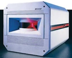
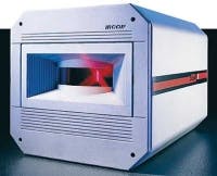
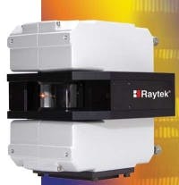
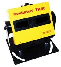
Today, three types of IR camera systems are available. The first, often termed electro-optical line-scanners, use single-element IR detectors and an electro-optical mechanical scan unit that revolves on a spindle to scan the field of view. As the spindle rotates, IR radiation enters through an aperture and is reflected onto an off-axis mirror that focuses the energy onto the IR detector. Its output is then digitized by an ADC and digital data processed, usually on-board the camera.
Such cameras, built by companies including Ircon, Raytek, and Thermoteknix, can be supplied with a number of different detector types depending on the wavelength of radiation to be detected (see Fig. 1). For its line of Centurion scanning IR detectors, for example, Thermoteknix has developed a variety of scanners based on indium gallium arsenide (InGaAs) and mercury cadmium telluride (MCT) detectors.
The company targets its MCT-based 3–5-μm TS50L scanner toward applications such as aluminum rolling at temperatures between 0–300°C; its InGaAs 1.45–1.55-μm TS50H model has been developed for higher-temperature 600–1300°C applications such as steel rolling. Because these types of sensors use electro-optics to digitize data, their fields of view are often configurable to as much as 100°C, with each scan line digitizing approximately 1000 data points.
Perhaps more important, resolution is specified not in terms of pixel size but spot size, which varies depending on how far the object being measured is placed from the camera. For example, Raytek has produced data showing that the spot size of one MWIR version of its MP150 series is approximately 1 in. when the scanner is placed 2.5 ft from an object and increases to 3 in. when the object is 10 ft away. This spot size becomes less of an issue with linescan cameras since they often need to measure very large objects such as kilns and must be placed many feet from the object to be measured.
Linear arrays
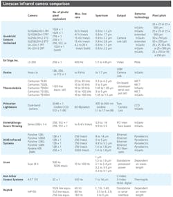
Rather than use single-point detectors and electro-optics, many companies are employing linear arrays in their linescan IR cameras. Here again, several companies offer these devices using a variety of detectors to capture different portions of the IR spectrum. Unlike electro-optical scanners, the resolution of these cameras is determined by the smallest size of pixel that is resolvable over the available field of view (see table).
On the other hand, the linear array benefits by capturing the image in all pixels simultaneously, with equal exposure time. This freezes motion; comparatively, a system that sweeps a virtual sensor across a moving object may obtain a skewed result. In addition, the swept system that is sampling n points across the image can only collect the light from each point for 1/n the time of a parallel array.
For instance, in its linescan cameras, Sensors Unlimited offers a variety of models, all based on InGaAs technology but offered in different formats to meet the needs of specific applications, which can range from machine vision of hot bottles and solar and semiconductor wafer inspection to the grooming of raw agricultural materials in order to eliminate contaminants.
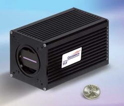
As part of the company’s product line, the SU-LD family of cameras can be supplied as 256 × 1-, 512 × 1-, or 1024 × 1-pixel linescan cameras that can operate at rates up to 92,000 lines per second (see Fig. 2). A pixel pitch of 25 × 25 μm with a precision mask is available for high time-resolution machine vision or, alternatively, with 50 × 50 µm for greater sensitivity. Pixel heights of 250 or 500 μm are offered for even greater sensitivity in some machine-vision applications and to match the shape of the spectrometer input slit for spectroscopy.
Standard front-illuminated InGaAs has a wavelength response of 0.8 to 1.66 µm, low dark current, and good thin-film properties, permitting low noise performance at room temperatures. By changing the ratio of indium to gallium in the InGaAs compound, the long wavelength response can be shifted out to 2.2 or even 2.6 µm but at the cost of higher dark current and more defects.
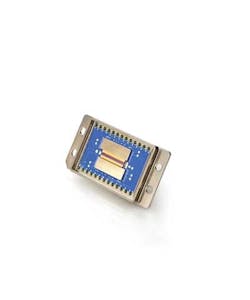
For its part, Xenics offers a number of IR cameras based on InGaAs technology. At present, these include cameras that use IR detectors of 128 × 1, 256 × 1, and 512 × 1 pixels with pixel pitches of 25 or 50 μm depending on the camera model. This month, however, the company announced its XLIN-1.7-1024 IR detector, which also uses InGaAs technology. The detector features a smaller 12.5-μm pixel pitch and a line rate of 40 kHz (see Fig. 3). According to Xenics, an IR camera based on this detector will be available in the second half of 2010.
Even with pixel sizes of 12. 5 × 12.5 μm, the smallest detectable object that can be resolved using such sensors and a lens with 1:1 magnification will be at least twice this, according to Nyquist sampling theory. Since IR cameras are generally placed at a distance from web inspection processes, specialized lenses may be required to even approach this resolution. However, in applications such as semiconductor inspection, high-magnification lenses can be used with cameras to find cracks and check the alignment of different layers within the semiconductor devices.
Web inspection
In web inspection processes, the line resolution achievable from the sensors may not be as important as the limiting resolution caused by the speed of the web process itself.
Depending on the speed of the web, both area array (FPA) sensors and linescan-based imagers can be used to detect emissivity or reflectance variations of the production process. Generally, however, the limiting frame rate of area-array-based IR imagers makes them unsuitable for such applications since captured images may be blurred due to the high-speed web process.
For example, if a web process is moving at approximately 4200 ft/min and is imaged with an area-array camera running at 30 frames/s, then during the exposure period the web will have moved approximately 28 in. during each frame acquisition. Thus, if the field of view is less than 28 in. in the direction of travel, some of the web content will not be imaged by the camera. However, if a linescan IR camera running at 5k lines/s were used in such an application, the web would move just 0.168 in. during line acquisition, allowing complete coverage of the web with minimum field of view in the direction of travel.
Thus, determining which IR camera will meet the demands of web-based applications involves understanding different types of camera systems, sensor resolutions, and implications of web inspection speeds. Before any temperature measurement can be made, IR cameras need to be calibrated to convert received intensity into temperature readings.
In developing their electro-optical scanners, companies such as Thermoteknix, Ircon, and Raytek incorporate blackbody radiators into their cameras, allowing them to be calibrated while in use. This is especially helpful in applications where the emissivity of the object being detected is not known, since the emitted radiation can be compared with a known blackbody radiator and thus the emissivity dynamically calibrated. Using integrated products, system developers can take advantage of the cameras’ on-board processing capability and software to quickly configure web-based applications.
For their part, linescan thermal IR camera manufacturers do not offer this kind of dynamic calibration, instead offering cameras that are precalibrated before shipping. While these cameras do not generally incorporate on-board blackbody radiators and CPUs, lower-cost alternatives must generally be configured with third-party IR image analysis software and blackbody calibration sources.
Company Info
Ann Arbor Sensor Systems
Ann Arbor, MI, USA
www.aas2.com
DIAS Infrared Systems
Dresden, Germany
www.dias-infrared.com
Entwicklungsbuero Stresing
Berlin, Germany
www.stresing.de
En’Urga
W. Lafayette, IN, USA
www.enurga.com
Goodrich/Sensors Unlimited
Princeton, NJ, USA
www.sensorsinc.com
Ircon
Santa Cruz, CA, USA
www.ircon.com
Princeton Lightwave
Cranbury, NJ, USA
www.princetonlightwave.com
Raytek
Santa Cruz, CA, USA
www.raytek.com
Thermoteknix
Cambridge, UK
www.thermoteknix.com
Xenics
Leuven, Belgium
www.xenics.com
